1State Key Laboratory of Precision Measurement Technology and Instruments, Department of Precision Instrument, Tsinghua University, Beijing 100084, China
2Division of Advanced Manufacturing, Graduate School at Shenzhen, Tsinghua University, Shenzhen 518055, China
Precise and fast determination of position and orientation, which is normally achieved by distance and angle measurements, has broad applications in academia and industry. We propose a dynamic three-degree-of-freedom measurement technique based on dual-comb interferometry and a self-designed grating-corner-cube (GCC) combined sensor. Benefiting from its unique combination of diffraction and reflection characteristics, the absolute distance, pitch, and yaw of the GCC sensor can be determined simultaneously by resolving the phase spectra of the corresponding diffracted beams. We experimentally demonstrate that the method exhibits a ranging precision (Allan deviation) of 13.7 nm and an angular precision of 0.088 arcsec, alongside a 1 ms reaction time. The proposed technique is capable of precise and fast measurement of distances and two-dimensional angles over long stand-off distances. A system with such an overall performance may be potentially applied to space missions, including in tight formation-flying satellites, for spacecraft rendezvous and docking, and for antenna measurement as well as the precise manufacture of components including lithography machines and aircraft-manufacturing devices.
1. INTRODUCTION
Precise geometric metrology, including the determination of positions and orientations, is essential to scientific research [1–3], remote sensing [4], and advanced manufacturing processes [5]. At present, the most accurate method of geometric measurement is based on interferometric phase measurement [6]. In this case, the geometrical parameters can be directly traceable to the wavelength of a continuous-wave (CW) laser. The optical phase of the emitted laser beam accumulates with the propagation of light waves and exhibits a period of rad, inducing phase wrapping ambiguity and hindering the observation of long-distance propagation. Therefore, to obtain multiple integers of the unambiguous phase, the continuous accumulation of instant phases based on incremental measurements is required. To expand the range of unambiguity, either the synthetic-wavelength method or the multiwavelength method may be applied. However, they both require several CW lasers, which encumber the system [7].
Over the past few decades, the advent of the optical-frequency combs (OFCs) has provided discrete and uniform mode-spacing narrow lines over wide spectra, constructing a series of stable CW lasers in the frequency domain [8,9]. Various OFC-based methods have been developed for phase measurement, e.g., the dispersive interferometry method [10,11], which uses the slope of the interferometric phase with respect to the optical frequency; the inter-mode beat method, which utilizes the harmonic phase of the pulse repetition rate of the OFC [12]; the pulse alignment method, which sweeps the pulse repetition rate [13]; and the dual-comb method [14–16]. Among them, the dual-comb method exhibits the advantages of being dynamic, highly precise, and having a large unambiguity range; therefore, it has been used as an efficient tool in optical metrology [17,18]. Usually, phase information is directly related to the distance of the target. In a multidimensional free space, pitch and yaw also serve as critical parameters that are used to determine the orientation of a target, e.g., the orientation of a satellite within a formation [19] and the orientations of constituent parts in aircraft assembly [20].
To realize high-precision distance and angle measurements, several improved phase measurement principles have been proposed, such as the multi-target interferometric method, the interferometric and autocollimation combined method, the Twyman–Green interferometer, and differential wavefront sensing [21–30]. However, each of the four methods suffers from particular shortcomings. Several targets need to be installed onto the target to be measured, and considerable distances need to be maintained between them to improve the accuracy of angle measurement via multi-target interferometric methods. As a result, a sufficiently large base is required in such cases, to which the required targets may be affixed [21]. The autocollimation method cannot be applied from long stand-off distances owing to the limitation of its objective lens’s aperture [23,24]. Differential wavefront sensing is only capable of detecting effective interference signals over small rotation ranges [26–29]. The Twyman–Green interferometer can be used to measure the displacement and rotation of the target by measuring the phase and amplitude spectra via a simple device. As in the case of differential wavefront sensing, the range of angle measurement is limited by the frequency resolution of the interference fringes [30]. In recent years, some OFC-based methods have been proposed for the measurement of distances and angles [31–35]. Compared to conventional methods, OFC-based methods are capable of addressing the problem of phase ambiguity and measuring absolute distances [32,33]. In addition, the wide spectral properties of the OFC can be utilized to increase the angle measurement range [34,35]. However, these methods are still based on the principles of autocollimation and interferometric methods, and they also suffer from the aforementioned problems. To the best of our knowledge, a three-degree-of-freedom (three-DOF) measurement technique capable of simultaneously exhibiting reasonable dynamics, precision, unambiguity range, stand-off distance, and compactness remains elusive.
Sign up for Photonics Research TOC. Get the latest issue of Photonics Research delivered right to you!Sign up now
In this paper, we propose a dynamic three-DOF measurement method based on dual-comb interferometry and a grating-corner-cube (GCC) combined sensor. The GCC combined sensor, which is specifically designed for the proposed implementation, consists of a two-dimensional transmission grating and a corner cube. When an incident beam passes through the GCC sensor, four first-order diffracted beams symmetrically distributed around the zeroth-order diffracted beam exit parallel to the incident beam. We convert the position and orientation information into three-dimensional phase spectra. Pitch and yaw angles can be accurately obtained by resolving the precise phase spectra of the first-order diffracted beams along the and axes. Moreover, the phase spectra of the zeroth-order diffracted beam can be used to measure absolute distances. By combining dual-comb interferometry with a diffracting corner cube, the proposed method exhibits simultaneous precise measurement of angles and absolute distances with large unambiguity range at a high refresh rate, enabling operation over long stand-off distances. Such an overall performance has potential applications in various scenarios including tight formation-flying satellites, spacecraft rendezvous and docking, antenna orientation measurement, lithography machines, and aircraft-manufacturing processes.
2. METHODS
A. Experimental Setup
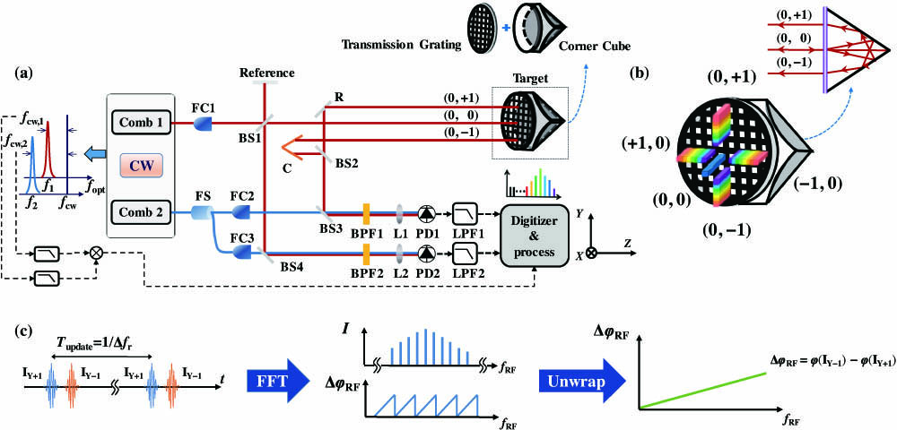
Figure 1(a) depicts the experimental setup and principle of the dual-comb spectroscopy resolved three-DOF measurement method. A transmission grating is tightly attached to the front surface of the corner cube to form a GCC sensor. A laser pulse train from Comb 1 (repetition frequency ) is incident on both the reference arm and the GCC sensor. The measured beam is diffracted by the transmission grating, and then the zeroth-order and st-order diffracted beams along the and directions are reflected by the corner cube. These five reflection beams are then diffracted by the transmission grating again. Obviously, as depicted in Fig. 1(b), their opposite-order (for instance, the original order is st and the opposite order is st) diffracted beams exit the GCC sensor parallel to the incident beam. The pulse train from Comb 2 (repetition frequency ), on the other hand, is evenly divided into three sampling pulses by a fiber splitters, and then they interfere with pulse trains from three paths. Here, the zeroth-order diffracted beam from the GCC sensor and the reflected beam from the reference arm can be utilized to measure the absolute distance along the -axis via the dual-comb ranging method [17]. In addition, the two other pulse trains from Comb 2 interfere with the two pulse trains in the direction and two pulse trains in the direction from the GCC sensor, respectively. Through linear optical sampling, the four pairs of interferograms (IGMs) (, , , ) are generated with a certain update time and finally sampled by two separate photodetectors (PDs) in their corresponding directions. In the frequency domain, it can be expressed as the multi-heterodyne process between the longitudinal modes in Comb 1, which can be expressed as , and the longitudinal mode in Comb 2, which can be expressed as , where represents the carrier-envelope offset frequency. After low-pass filtering from 0 to , a series of heterodyne signals in the radio frequency (RF) domain with spacing can be obtained.
Figure 1.(a) Schematic of the experimental setup. FC1–FC3, fiber collimator, the collimated beam diameter is ; FS, fiber splitter; R, reflection mirror; BS1–BS4, nonpolarizing beam splitter; C, corner cube; BPF1 and BPF2, band-pass filter, the bandwidth is 5 nm to avoid spectral aliasing; LPF1 and LPF2, low-pass filter from 0 to ; L1 and L2, focusing lens; PD1 and PD2, photodetector (model: 1811-FS, Newport). Diffracted beams with various frequency modes are focused by the lens and then sampled by the PD. The of both OFCs are fully stabilized by interferometers (). (b) The transmission grating is tightly attached to the front surface of the corner cube. The zeroth-order diffracted beam, two first-order diffracted beams in the direction, and two first-order diffracted beams in the direction exit the GCC sensor parallel to the incident beam after being twice diffracted by the grating and once reflected by the corner cube. The GCC sensor in view is also depicted. (c) Data processing in dual-comb interferometry. Two IGMs, and , with a measurement period of . The amplitude and phase spectra of the IGMs can be calculated by FFT.
As depicted in Fig. 1(c), based on the dual-comb method, the pitch angle () can be calculated from the phase difference between and using a fast Fourier transform (FFT). Here, only the view is depicted in Fig. 1(a); the yaw angle () can also be obtained using the phase difference between and in the view. Compared to the initial setup reported in the conference proceedings [36], to achieve stable phase spectra, we use a free-running continuous-wave (CW) laser with a frequency of (model: RIO0195, Rio, Inc.) as an optical intermediary to obtain the beat signal between two combs and thus calculate the envelope timing jitter and carrier phase noise of the IGMs. Through a digital postcorrection, the frequency noise of all the IGMs can be compensated [37]. Furthermore, to further decrease the effect of random noises, the corner cube (C) is used to adjust the time delay between and and make them approximately equal [38]. In the experiments, we use the multipulse sampling technique to realize the multiplication of IGMs [39]. The multiplication factor is set to 8, and thus the precision of both d/df and is increased by a factor .
B. Fabrication of the GCC Sensor
For the GCC sensor, limited by the maximum incident angle of the corner cube, the grating period should be longer than that of ordinary gratings. However, for the conventional holographic exposure method, fabricating a grating with a long period is difficult. Using a compact improved dual-beam exposure system, we fabricated a two-dimensional grating with a period () of 5 μm and an aperture of 50 mm. The diffraction efficiency can reach 10%. Because of the small off-axis of the pinholes, the symmetrical design of the system, and the use of an aspherical lens as collimation lens, the interference aberration of this exposure system is very small, and thus it is able to fabricate a grating with spacing error of only 0.03g. More details regarding the design and fabrication method of the grating are provided in our previous work [40]. The self-designed grating is tightly attached to the front surface of the commercial corner cube (model: PS976-C, Thorlabs, Inc.) constructed using N-BK7 materials with a diameter of 50 mm to form a GCC sensor.
C. Theoretical Models
According to the reflection characteristics of the corner cube, the model of a GCC sensor is equivalent to a parallel grating pair (G and ) as illustrated in Fig. 2(a). Here is the virtual image of G. To measure the orientation of the combined sensor, based on the right-hand rule, we establish the space coordinate system with its origin at the intersection of the incident beam and the grating. Two coordinate systems are involved in this model: one is the world coordinate system, which remains unchanged, and the other is the grating coordinate system, where the and axes are along the two periodic directions of the grating, respectively, and the axis is along the normal direction of the grating. In the initial state, these two coordinate systems are completely coincident, and afterward, the grating coordinate system will change with a three-DOF rotation. The incident beam in the world coordinate system can be expressed as . When the matrix that expresses the rotated coordinate system of the , , and axes is considered in a clockwise direction, the rotation matrixes, relative to an original coordinate, are as follows: where , , and represent the rotation angles in the , , and axes, respectively. Any rotation can be expressed as a composition of rotations about the three axes and thus can be represented by a matrix operating on a vector:
Figure 2.Theoretical model of the present method. (a) Schematic diagram of the GCC sensor in the space coordinate system. (b) Simulated versus and . Simulated versus and . The grating pair spacing , μ, , , and . (c) Simplified theoretical model. denotes the frequency of the th longitudinal mode. and are the diffraction angles of the (0, )-order diffracted beam before and after rotation, respectively. (d) Principle of angle measurement method associated with the near-infrared (NIR) frequency comb. denotes the diffraction angle of the th longitudinal mode, . denotes the repetition period of Comb 1.
Thus, after three-DOF rotation, the incident beam in the grating coordinate system can be expressed as . As Fig. 2(a) depicts, the unit vector of the ()-order diffracted beam is . In the grating coordinate system, . Here can be expressed using the unit vector of the incident beam according to the diffraction equation where denotes the grating period, denotes the refractive index of the th longitudinal mode in the corner cube, denotes the phase refractive index of the th longitudinal mode in air, and denotes the wavelength of the th longitudinal mode. Before and after rotation, the phase change can be obtained using the optical path difference , and the grating translations and along the two periodic directions: Here we use the phase difference of st-order and st-order diffracted beams to improve the sensitivity and eliminate the crosstalk error of axial distance. The corresponding phase difference of the th longitudinal mode in the and directions can be obtained using First, numerical simulations of the relation between , and , in the range of were conducted, respectively. Here is set to 191.208 THz, which is equal to the carrier frequency of Comb 1. As depicted in Fig. 2(b), and were observed to be relatively independent and affected only by and , respectively. The crosstalk error was lower than 0.02 arcsec within a range of . To simplify the theoretical model, the crosstalk error can be ignored in the case of a small rotation; thus, two-dimensional rotation can be regarded as two independent one-dimensional rotations. We can measure the pitch angle by the phase changes of (0, )- and (0, )-order diffracted beams. Similarly, the yaw angle can be obtained using the phase changes of (, 0)- and (, 0)-order diffracted beams. Because the transmission grating has an identical grating period in the and directions, the theoretical models of and are also equivalent.
Here we take as an example. Figure 2(c) depicts the parallel grating pair in the view. We set rotation point at position O for simplicity; that is, the intersection of the incident beam and grating is assumed to be the turning point. The blue lines represent the initial state, and the long sides G and represent a pair of parallel gratings. In this case, the laser beam is normally incident onto the transmission grating at point O. The (0, )-order diffracted beam and (0, )-order diffracted beam are then diffracted by the grating at points A and B, respectively. We rotate the grating pair from 0 to , as illustrated in the yellow lines. The position of the first diffraction remains unchanged at point O. Because of the change in diffraction angle, the (0, )-order diffracted beam and (0, )-order diffracted beam are then diffracted by the grating at points and , respectively. Obviously, their opposite-order diffracted beams exit parallel to the incident beam. Before and after rotation, the phase change can be obtained using the optical path difference and the grating movement along the periodic directions of the second grating.
When is a small angle, the phase difference is considered. Equation (8) can be approximated as a linear equation where denotes the grating pair spacing, and and are the diffracted angles of the (0, )- and (0, )-order diffracted beams under normal incidence. Considering the diffracted equation , the relationship between the angle of rotation and the phase change is given as follows: where denotes the speed of light in a vacuum. Therefore, the relationship between the rotation angle and carrier phase difference is given: where denotes the refractive index of the center wavelength in the corner cube and denotes phase refractive index of the center wavelength in air. As Eq. (12) depicts, because the linear slope is constant, can be easily obtained through the calculation of the carrier phase difference. However, the unambiguity range of interferometric measurement is only . As Fig. 2(d) depicts, the different longitudinal modes of the incident beam are spatially separated into a group of first-order diffracted beams with different diffraction angles depending on their optical frequencies. When the angle of the target sensor changes, different longitudinal modes will suffer different phase changes. Therefore, a simple linear fit between and can give an expanded unambiguity range. The phase-frequency slope can be approximately expressed using the partial differential of Eq. (11) at the carrier frequency :
Here the approximate errors of Eqs. (12) and (13) are better than 0.007 arcsec and 0.06 arcsec within ±1500 arcsec, respectively, which are much lower than the errors caused by phase noise and phase-frequency slope noise in dual-comb system. Therefore, using the phase frequency slope, we can measure the value of roughly. Through the use of the carrier phase difference, a more precise can be obtained. In particular, all parameters in Eqs. (12) and (13) can be explicitly calculated. Among them, and are calculated using the Sellmeier equation for N-BK7 materials. is calculated using the Edlén equation. is measured via the optical diffraction method. denotes the grating pair spacing, which is equal to twice the distance between the front surface of the grating and the vertex of the corner cube and can be measured via the dual comb ranging method. can be calculated based on the repetition frequency, the carrier-envelope offset frequency, and the serial number of the longitudinal mode. Here the repetition frequency and the carrier-envelope offset frequency are parameters of the OFC, traced to the atomic clock, and can be obtained accurately. Therefore, the angle results can be obtained directly through the phase spectra. It should be noted that the above analysis is also suitable for .
Here, if the rotation point is not at position O, there is an additional phase shift caused by the movement of grating G. However, this additional phase shift will be compensated by the phase shift of grating , such that the phase changes of the exit beams are sensitive only to the angle variation. As a result, the precisions of and can both reach subarcsecond level with the reaction time, at millisecond scale, by the phase spectra of the diffracted beams in the direction and direction, respectively.
3. RESULTS
A. Stability Tests
To test the measurement performance, the stability results were first obtained at a stand-off distance of . Figure 3 presents the angular precision (Allan deviation) and ranging precision of both the time-of-flight (TOF) method, by the use of , and the carrier-wave interferometric (CWI) method, by the use of versus different averaging time. Here the precisions of and are both determined mainly by the phase noise caused by the instability of cavity length of the laser source, and they are nearly the same. Therefore, only the precision of was analyzed. In the experiments, the grating period μ, and the carrier frequency . and . . The grating pair spacing . Therefore, we can obtain that (CWI method), in which the unit of is radians. The equation can be further simplified to , in which the unit of is arcseconds. Similarly, we also can obtain that (TOF method), in which the unit of is arcseconds. As depicted in Fig. 3(a), the precision of the TOF method is roughly arcsec × , which is caused by approximately instability of . The precision of the CWI method is roughly arcsec × , corresponding to the 0.07 rad × precision of the carrier phase difference, reaching 0.0094 arcsec at 100 ms and 0.0041 arcsec when it continues to average 0.5 s. It should be noted that, with 560 ms averaging time, the result of the TOF method is stable enough to determine the integer of the unambiguity angle, and thus an angle measurement with large unambiguity range can be achieved.
Figure 3.Precision (Allan deviation) versus averaging time, computed from 2 s length data. Both the TOF and CWI measurement results of angle and absolute distance are given. The half-unambiguity angle is 3.91 arcsec [calculated by from Eq. (12)]. The half-unambiguity distance is a quarter-carrier wavelength ().
For absolute distance, as Fig. 3(b) depicts, the TOF ranging precision and CWI ranging precision in the dual-comb ranging method are 2.2 μm × and 13.5 nm × , respectively. The TOF result is sufficiently stable to link to the CWI method after 40 ms averaging period. In this case, meter-scale measurement range and nanometer-scale precision can be achieved.
B. Comparison Experiments
Moreover, we made a linear comparison with a commercial autocollimator (Collapex 200, AcroBeam, resolution 0.01 arcsec, 0.3 arcsec accuracy within ). The GCC sensor and the plane mirror of the autocollimator were mounted on the two-axis precision rotary stage for investigating the linear and random errors of the proposed method. The comparison range for both directions was 200 arcsec with a step of 10 arcsec. The pitch and yaw angles of the rotary stage were detected simultaneously using the proposed method and the commercial autocollimator. For each position, the data were recorded for 1 s, and the average results were used for the comparison of and , respectively. During the comparison, the environmental parameters were recorded to correct for the effect of the refractive index of air (). As depicted in Figs. 4(a) and 4(b), the results of the present system are in good accordance with the “standard results” of the commercial autocollimator. Through the application of linear fitting, the slopes and the correlation coefficients () in the and directions are determined to be 1.0012 and 0.9999987, and 0.9857 and 0.9999989, respectively. The linear errors are primarily caused by spacing errors of the grating, the grating profile error, the nonflatness of the substrate, the surface error of the corner cube, and the misalignment of the measurement axes used in the proposed method and the reference autocollimator. Further, the random errors of the proposed method were also evaluated. As depicted in Fig. 4(a), the comparison residuals of the pitch angle range between and 0.24 arcsec, with a standard deviation of . As depicted in Fig. 4(b), the comparison residuals of the yaw angle range between and 0.19 arcsec, with a standard deviation of .
Figure 4.(a) Pitch angles () obtained via the proposed method versus those obtained via the commercial autocollimator. (b) Yaw angles () obtained via the proposed method versus those obtained via the commercial autocollimator.
C. Dynamic and Resolution Measurements Implementation
To further verify the dynamic performance and resolution of the proposed method, both the distances and the angles measured from a stand-off distance of 1.12 m and a stand-off distance of 11.35 m were given. The GCC sensor was mounted on a six-axis piezo stage (model P-562, PI, Inc.) with capacitive sensors (angle resolution: 0.02 arcsec, distance resolution: 1 nm) in closed-loop mode. At a stand-off distance of , the GCC sensor was made to undergo continuous linear and rotational motions under a 10 Hz modulation frequency with modulation amplitudes of 50 nm and 0.3 arcsec, respectively. Corresponding to each modulation, the data were recorded for 1 s, and the distance () and tilt angle () were simultaneously measured via the proposed method and the capacitive sensor installed inside the piezo stage. As depicted in Figs. 5(a) and 5(b), the results obtained via the proposed method correspond well to the results obtained via the capacitive sensor, and continuous sinusoidal motions of 50 nm and 0.3 arcsec were clearly observed and reconstructed. As the minimum reaction time of the proposed method is known to be , under relatively low-speed measurement conditions, coherent averaging can be used to further reduce the random noise. It is evident that after averaging over 5 ms, the proposed method was able to distinguish the continuous sinusoidal motions more clearly. The angle and distance results measured from a relatively long stand-off distance of 11.35 m were both given. The GCC sensor was made to undergo continuous linear and rotational motions under a 25 Hz modulation frequency with modulation amplitudes of 1 μm and 0.4 arcsec, respectively. As depicted in Fig. 5(c), the ranging resolution was reduced to μ due to environmental disturbances over long distances. In this case, the angular resolution of 0.4 arcsec could still be attained because of the approximate common optical path of st-order diffracted beams.
Figure 5.Dynamic and resolution results. (a) Resolution results of distance under 10 Hz modulation at . (b) Resolution results of angle under 10 Hz modulation at . (c) Resolution results of distance under 25 Hz modulation at . (d) Resolution results of angle under 25 Hz modulation at .
As mentioned previously, the linear errors of and exhibit a slight difference, some of which are induced by different grating spacing errors in the two dimensions. When an incident beam passes through the GCC sensor, the first and second diffraction sites at the transmission grating are different. Because of the spacing errors, the grating periods of the two diffraction sites are also different, which affects the angle of diffraction and induces the phase change. If only the effect of the spacing error on the linear errors is considered, the grating period difference between the and directions amounts to . Here we primarily consider low-frequency errors induced by the grating because the diameter of the input beam is , which corresponds to grating lines. Therefore, the influence of high-frequency spacing errors can be considered to be negligible. Considering that the diffracted beams are the transmission orders of the two-dimensional grating, the phase of diffracted beams will be affected by the grating profile error, the nonflatness of the substrate, and the surface error of the corner cube. Due to the different paths of different orders’ diffracted beams inside the GCC sensor, the effects of the aforementioned errors for diffracted beams in the and directions are also different. Moreover, the misalignment of the measurement axis of the proposed method and the reference autocollimator caused by orthogonality errors of the grating lines on the and axes also introduces different linear errors. For practical application, the linear errors caused by the fabrication of the GCC sensor can be compensated by calibration. Further reduction of fabrication error of the GCC sensor will also be investigated in a future work.
In a dual-comb system, the minimum reaction time is known to be . High-repetition-frequency systems [gigahertz (GHz) level or higher] exhibit large values of (approximately 10–100 MHz), inducing reaction times between 10 and 100 ns [14]. To further improve the dynamic performance, high-repetition-frequency combs can be utilized, which also decrease phase noise and timing jitter, thereby improving the precision of both the TOF and CWI methods.
To achieve the simultaneous measurement of distance and two-dimensional angles, the five parallel measurement beams are required to be separated in space. Therefore, the maximum stand-off distances of the proposed method are mainly limited by the diameter of the collimated beam before passing the GCC sensor. Based on the divergence angle of the commercial fiber collimator, the diameter of the collimated beam is about a few millimeters to tens of millimeters in the distance from tens to hundreds of meters. For a longer stand-off distance (a few kilometers and longer), the proposed method is possible to be realized by increasing the size of the target. To further increase the maximum stand-off distance, the processing of the large-scale grating and the corner cube will also be investigated.
In conclusion, in this study, we have proposed a three-DOF measurement method. Using the dual-comb technique and a self-designed GCC combined sensor, the absolute distance, pitch, and yaw of a target can be determined based on the phase spectra of corresponding diffracted beams. The proposed method was verified to be capable of dynamically measuring distances and angles with high precision and resolution. Further, it can be applied from long stand-off distances because all the measurement beams emitted by the GCC sensor are parallel to the incident beam, irrespective of the orientation or translation of the target. By using a compact target, the proposed method can realize subarcsecond-scale precision in pitch and yaw angle measurements and nanometer-scale precision in distance measurements, with millisecond-scale reaction times, large unambiguity ranges, and long stand-off distances. Such an overall performance brings great benefits to various tasks in optical metrology, such as space missions and precise manufacturing.
Acknowledgment
Acknowledgment. We thank Professor Lifeng Li and Professor Lijiang Zeng from Tsinghua University for their help in grating diffraction theory and grating fabrication, respectively. We also thank Professor Yang Li from Tsinghua University for helpful comments on this manuscript.
[36] S. Zhou, Z. Zhu, S. Xiong, K. Ni, Q. Zhou, G. Wu. Dual-comb based angle measurement method using a grating and a corner cube combined sensor. Conference on Lasers and Electro-Optics Pacific Rim (CLEO-PR), W4F.5.(2018).