
Juncheng Fang, Jinpei Li, Aru Kong, Youpeng Xie, Chuxuan Lin, Zhenwei Xie, Ting Lei, Xiaocong Yuan, "Optical orbital angular momentum multiplexing communication via inversely-designed multiphase plane light conversion," Photonics Res. 10, 2015 (2022)
- Photonics Research
- Vol. 10, Issue 9, 2015 (2022)
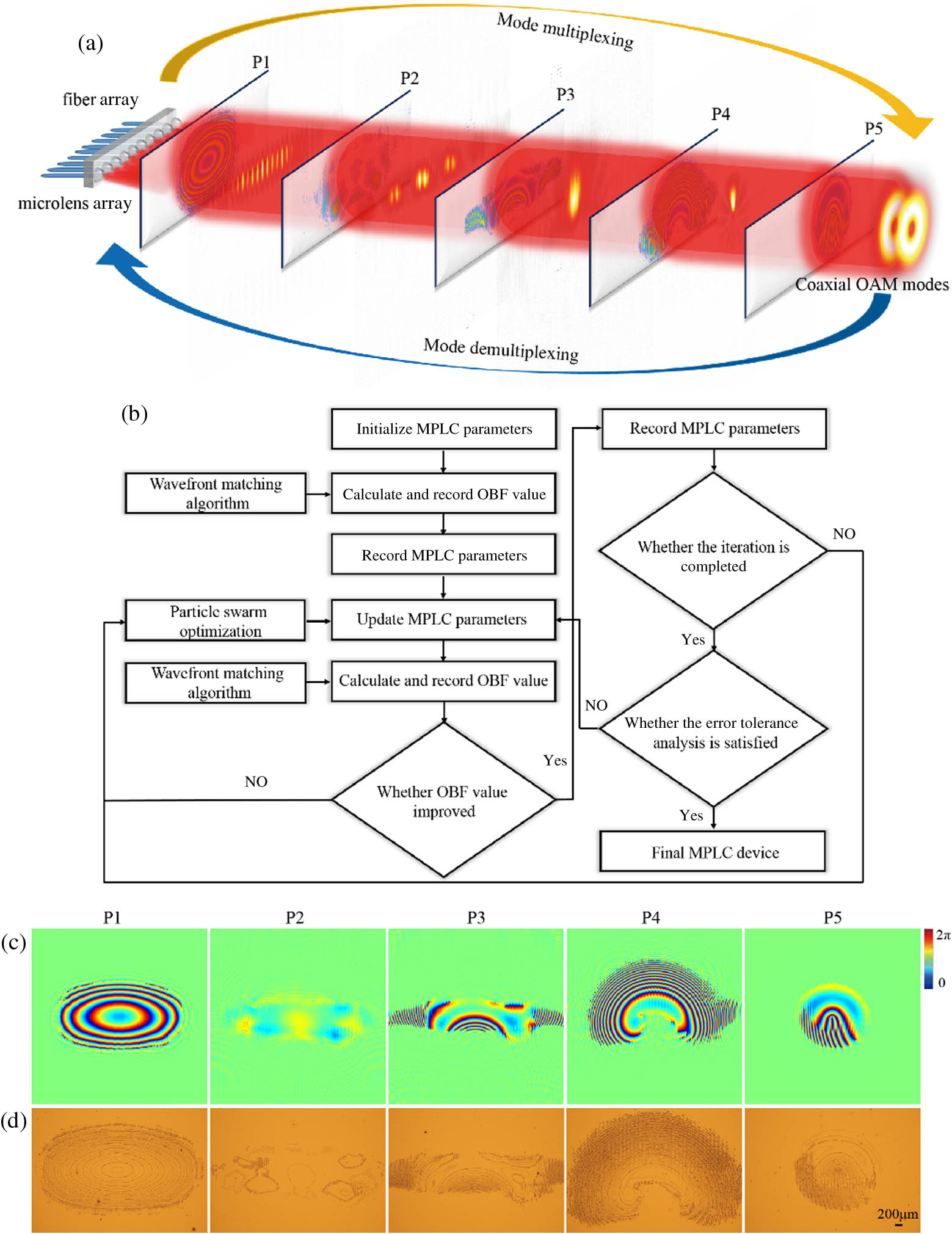
Fig. 1. OAM mode transformation via an inversely-designed multiphase plane light conversion. (a) Multiphase planes are designed to perform reversible mode conversion between multiple axial OAM modes and a Gaussian spot array. (b) MPLC optimization flowchart; OBF, optimization objective function. (c) Phase distributions for the five designed phase planes. (d) Corresponding microscopic images of the fabricated devices.
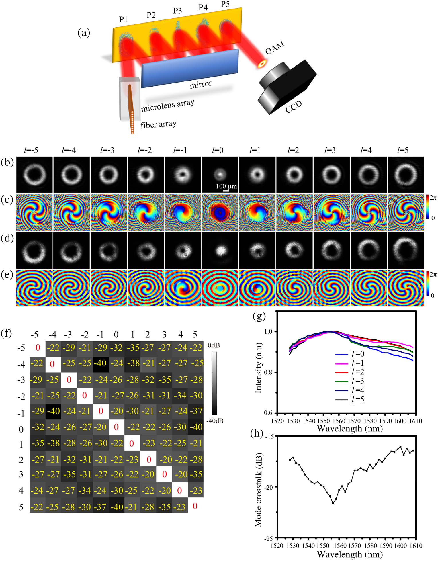
Fig. 2. (a) Reflective OAM multiplexer based on MPLC. Calculated images of (b) the OAM intensity profile and (c) the phase of the OAM. (d) Intensity profiles of the OAM generated by MPLC in the experiments. (e) Reconstructed phase profiles for the OAM generated from off-axis holography. (f) Measured mode crosstalk matrix for the OAM. (g) Conversion efficiency and (h) maximum mode crosstalk of the OAM multiplexer over the C-band and the L-band wavelengths.
Fig. 3. (a) OAM generated by MPLC is transmitted in few-mode fiber. (b) Input OAM from − 3 − 3 + 3
Fig. 4. (a) Experimental setup for OAM multiplexing-based fiber communication using MPLC; PPG, programmable pulse generator; MZM, Mach–Zehnder modulator; PC, polarization controller; VOA, variable optical attenuator; EDFA, erbium-doped fiber amplifier; BPF, bandpass filter; PD, photodetector; PED, programmable error detector. (b) Measured BERs of the multiplexed coaxial OAM mode channels in 5 km few-mode fiber communications; eye diagrams of OAM for (c) l = 1 l = 3
Fig. 5. MPLC device fabrication procedure.
Fig. 6. Characterization apparatus of MPLC. (a) Setup of MPLC off-axis digital holography. (b) Interference pattern of OAM.


Set citation alerts for the article
Please enter your email address

© Copyright 2018-2021 | Chinese Laser Press. All Rights Reserved 沪ICP备15018463号-20