
Juncheng Fang, Jinpei Li, Aru Kong, Youpeng Xie, Chuxuan Lin, Zhenwei Xie, Ting Lei, Xiaocong Yuan, "Optical orbital angular momentum multiplexing communication via inversely-designed multiphase plane light conversion," Photonics Res. 10, 2015 (2022)
- Photonics Research
- Vol. 10, Issue 9, 2015 (2022)
Abstract
1. INTRODUCTION
In 1992, Allen
Among these OAM (de)multiplexing techniques, multiphase plane light conversion (MPLC) [44–49], optical neural networks [50,51], and machine learning [52,53] are drawing increasing attention because of their solid performance levels and high flexibility. However, the number of phase planes required affects the practical performance, especially in terms of the mode conversion efficiency [44,49]. For symmetrical modes such as Hermit–Gaussian modes, the number of phase planes can be reduced greatly by introducing a symmetrical boundary condition [47,48]. For OAM modes, it is expected to achieve efficient and low crosstalk (de)multiplexing via inversely-designed MPLC.
In this work, we propose and demonstrate an OAM multiplexing communication technique based on MPLC that can enable perfect OAM (de)multiplexing by using a set of inversely-designed phase planes through a wavefront-matching algorithm. The proposed configuration only requires five phase planes to accomplish both OAM mode multiplexing and demultiplexing perfectly. These phase planes are fabricated on a silicon wafer using three cycles of a mask lithography procedure. The sorted pattern is a near-perfect Gaussian beam that is compatible with the base mode of a single-mode fiber and can be coupled easily into a single-mode fiber. Conversely, the light coming from a single-mode fiber array will be converted into a series of coaxial OAM modes after passing through the five phase planes. The mode conversion performed through these five optimized phase planes provides high-quality demultiplexing spots, high process efficiency, and low mode crosstalk. More importantly, the proposed configuration is both a perfect mode sorter and a perfect mode multiplexer simultaneously. In addition, the bit-error-rate (BER) curve shows that the OAM (de)multiplexer based on MPLC offers high performance for fiber communications.
Sign up for Photonics Research TOC. Get the latest issue of Photonics Research delivered right to you!Sign up now
2. PRINCIPLE AND MODE ANALYSIS OF INVERSELY-DESIGNED MPLC
The OAM multiplexer presented here converts multiple channels of independent input Gaussian beams into corresponding high-order coaxial OAM modes. There is no analytic function expression for inversely-designed MPLC when using the wavefront-matching method. The OAM multiplexer based on the MPLC method realizes its mode conversion function by using multiple phase planes, and the phase distribution of the phase plane can be calculated using the wavefront-matching algorithm. Wavefront matching means that forward-propagating light fields should be matched with backward-propagating light fields at any position in the space. In the wavefront-matching algorithm, the phase distribution of the phase plane
The input light field and the output light field can be determined by using the angular spectrum algorithm. The phase plane is updated, and the iterative calculation involved is repeated until the algorithm converges to provide the phase distribution of the phase plane.
Figure 1(a) shows a schematic of the OAM multiplexer based on inversely-designed MPLC. The inverse-design process is sensitive to the initial value of the phase mask and is oriented via algorithm optimization. We establish our optimization objective function by determining the best conversion efficiency for the light field that is given by the overlapping integral between the generated mode and the ideal mode
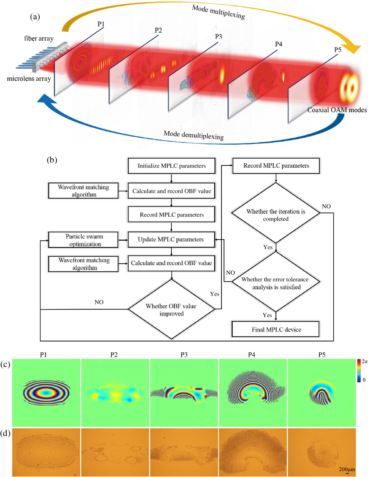
Figure 1.OAM mode transformation via an inversely-designed multiphase plane light conversion. (a) Multiphase planes are designed to perform reversible mode conversion between multiple axial OAM modes and a Gaussian spot array. (b) MPLC optimization flowchart; OBF, optimization objective function. (c) Phase distributions for the five designed phase planes. (d) Corresponding microscopic images of the fabricated devices.
The phase mask is composed of five phase planes, each of which has dimensions of
3. EXPERIMENTAL RESULTS AND ANALYSIS
The reflective OAM multiplexer is shown in Fig. 2(a), where the phase mask for the OAM (de)multiplexer contains five phase planes. The fiber array and the microlens array output 11 collimated Gaussian beams that pass through five phase planes accurately by adjusting the phase mask and the mirror [49]. The pitch for the fiber array and the microlens array is 250 μm. The distance between the light source and the first phase plane is 44 mm; the distance between adjacent phase planes is 70 mm. The waist diameter of the input beam is 110 μm; the waist diameter of the output beam is 400 μm. The 11 Gaussian beams are input into different positions in the OAM multiplexer and converted into the
![]()
Figure 2.(a) Reflective OAM multiplexer based on MPLC. Calculated images of (b) the OAM intensity profile and (c) the phase of the OAM. (d) Intensity profiles of the OAM generated by MPLC in the experiments. (e) Reconstructed phase profiles for the OAM generated from off-axis holography. (f) Measured mode crosstalk matrix for the OAM. (g) Conversion efficiency and (h) maximum mode crosstalk of the OAM multiplexer over the C-band and the L-band wavelengths.
The measured phases of the OAM are consistent with the calculated phases of the OAM. By a process of correlation of all the generated OAM, we extracted the OAM crosstalk matrix, as shown in Fig. 2(f). The mode crosstalk of the OAM generated by MPLC is less than
MPLC can also be used in OAM demultiplexing. The MPLC technique based on inverse design must design the phase plane according to the incident beam waist diameter, which places strict requirements on the incident beam. Few mode fibers can be encapsulated in a graded index lens (G-lens) and control the beam waist diameter based on the focal length of G-lens. Therefore, the OAM generated by the OAM multiplexer is coupled to the few-mode fiber via a G-lens, and the total system loss is less than 12 dB. The commercial few-mode fiber used is a step-type fiber with a core diameter of 16 μm that supports OAM transmission from the
![]()
Figure 3.(a) OAM generated by MPLC is transmitted in few-mode fiber. (b) Input OAM from
In this work, we have demonstrated OAM multiplexing communication based on two MPLC devices, where one was used as an OAM multiplexer and the other used as an OAM demultiplexer. Figure 4(a) shows the experimental setup for OAM multiplexing-based fiber communication using MPLC. A 1550 nm laser beam is modulated to carry a 10 Gbit/s on–off keying signal from a pattern generator; this beam is then split into two branches using a coupler. Two channels are then converted to produce coaxial OAM via an OAM multiplexer. The G-lens couples the coaxial OAM to a few-mode fiber for transmission over 5 km. The coaxial OAM is incident on the OAM demultiplexer from the G-lens at the other end of the few-mode fiber. The polarization controller is then adjusted carefully to ensure that the OAM is demultiplexed sufficiently. The coaxial OAM demultiplexing results are coupled into a single-mode fiber array for BER testing. Figure 4(b) shows the BER of coaxial OAM communication in 5 km few-mode fiber with the power penalties less than 10 dB. The BER curve illustrates that the OAM (de)multiplexer based on MPLC is suitable for use in optical fiber communications. Figures 4(c) and 4(d) show the eye diagrams for the OAM topological charges of 1 and 3, respectively. The eye diagrams for two OAM channels are both with clear opens and small slopes, which indicate the excellent performance of MPLC in OAM multiplexed communication. The big opens show the good signal-to-noise ratio, and the crossings illustrate the small jitter of the signal. The similarity between the two diagrams indicates a consistent good performance of MPLC device over all the multiplexing OAM channels.
![]()
Figure 4.(a) Experimental setup for OAM multiplexing-based fiber communication using MPLC; PPG, programmable pulse generator; MZM, Mach–Zehnder modulator; PC, polarization controller; VOA, variable optical attenuator; EDFA, erbium-doped fiber amplifier; BPF, bandpass filter; PD, photodetector; PED, programmable error detector. (b) Measured BERs of the multiplexed coaxial OAM mode channels in 5 km few-mode fiber communications; eye diagrams of OAM for (c)
4. CONCLUSION
In summary, we have proposed and experimentally demonstrated an OAM mode (de)multiplexer based on inversely-designed MPLC. The proposed device is shown to be a good OAM mode multiplexer and a good mode sorter. After passing through the five phase planes, the coaxial OAM modes can be transferred smoothly into spatially separated Gaussian beams and vice versa. The mode (de)multiplexing process shows an insertion loss of less than 2.6 dB and mode crosstalk less than
Acknowledgment
Acknowledgment. The authors would like to acknowledge the Photonics Center of Shenzhen University for providing technical support.
APPENDIX A: MPLC DEVICE FABRICATION
The optimized five phase planes [P1, P2, P3, P4, and P5 in Fig.
![]()
Figure 5.MPLC device fabrication procedure.
APPENDIX B: OFF-AXIS HOLOGRAPHIC RECONSTRUCTION OF OAM PHASE
In the experiment, we reconstructed the amplitude and phase of the OAM mode profile generated by the device using an off-axis digital holography [Fig.
![]()
Figure 6.Characterization apparatus of MPLC. (a) Setup of MPLC off-axis digital holography. (b) Interference pattern of OAM.
By the correlation among all the generated OAM, we extract the OAM crosstalk matrix for the OAM as shown in Fig.
References
[1] L. Allen, M. W. Beijersbergen, R. J. C. Spreeuw, J. P. Woerdman. Orbital angular momentum of light and the transformation of Laguerre-Gaussian laser modes. Phys. Rev. A, 45, 8185-8189(1992).
[2] M. Padgett, J. Arlt, N. Simpson. An experiment to observe the intensity and phase structure of Laguerre-Gaussian laser modes. Am. J. Phys., 64, 77-82(1996).
[3] B. Spektor, A. Normatov, J. Shamir. Singular beam microscopy. Appl. Opt., 47, A78-A87(2008).
[4] J. Masajada, M. Leniec, E. Jankowska, H. Thienpont, H. Ottevaere, V. Gomez. Deep microstructure topography characterization with optical vortex interferometer. Opt. Express, 16, 19179-19191(2008).
[5] I. Gianani, A. Suprano, T. Giordani, N. Spagnolo, F. Sciarrino, D. Gorpas, V. Ntziachristos, K. Pinker, N. Biton, J. Kupferman. Transmission of vector vortex beams in dispersive media. Adv. Photon., 2, 036003(2020).
[6] M. P. Lavery, F. C. Speirits, S. M. Barnett, M. J. Padgett. Detection of a spinning object using light’s orbital angular momentum. Science, 341, 537-540(2013).
[7] W. Wang, T. Yokozeki, R. Ishijima, A. Wada, Y. Miyamoto, M. Takeda, S. G. Hanson. Optical vortex metrology for nanometric speckle displacement measurement. Opt. Express, 14, 120-127(2006).
[8] D. G. Grier. A revolution in optical manipulation. Nature, 424, 810-816(2003).
[9] E. Otte, C. Denz. Optical trapping gets structure: structured light for advanced optical manipulation. Appl. Phys. Rev., 7, 041308(2020).
[10] D. Mao, Y. Zheng, C. Zeng, H. Lu, C. Wang, H. Zhang, W. D. Zhang, T. Mei, J. L. Zhao. Generation of polarization and phase singular beams in fibers and fiber lasers. Adv. Photon., 3, 014002(2021).
[11] R. Fickler, R. Lapkiewicz, W. N. Plick, M. Krenn, C. Schaeff, S. Ramelow, A. Zeilinger. Quantum entanglement of high angular momenta. Science, 338, 640-643(2012).
[12] J. C. Garcia-Escartin, P. Chamorro-Posada. Quantum multiplexing with the orbital angular momentum of light. Phys. Rev. A, 78, 5175-5179(2008).
[13] A. Nicolas, L. Veissier, L. Giner, E. Giacobino, D. Maxein, J. Laurat. A quantum memory for orbital angular momentum photonic qubits. Nat. Photonics, 8, 234-238(2014).
[14] X. L. Wang, X. D. Cai, Z. E. Su, M. C. Chen, D. Wu, L. Li, N. L. Liu, C. Y. Lu, J. W. Pan. Quantum teleportation of multiple degrees of freedom of a single photon. Nature, 518, 516-519(2015).
[15] D. Cozzolino, E. Polino, M. Valeri, G. Carvacho, D. Bacco, N. Spagnolo, L. K. Oxenlowe, F. Sciarrino. Air-core fiber distribution of hybrid vector vortex-polarization entangled states. Adv. Photon., 1, 046005(2019).
[16] J. Wang. Advances in communications using optical vortices. Photon. Res., 4, B14-B28(2016).
[17] S. Yu. Potentials and challenges of using orbital angular momentum communications in optical interconnects. Opt. Express, 23, 3075-3087(2015).
[18] A. M. Yao, M. J. Padgett. Orbital angular momentum: origins, behavior and applications. Adv. Opt. Photon., 3, 161-204(2011).
[19] X. Y. Fang, H. C. Yang, W. Z. Yao, T. X. Wang, Y. Zhang, M. Gu, M. Xiao. High-dimensional orbital angular momentum multiplexing nonlinear holography. Adv. Photon., 3, 015001(2021).
[20] Y. J. Shen, X. J. Wang, Z. W. Xie, C. J. Min, X. Fu, Q. Liu, M. L. Gong, X. C. Yuan. Optical vortices 30 years on: OAM manipulation from topological charge to multiple singularities. Light Sci. Appl., 8, 90(2019).
[21] J. Wang, J. Y. Yang, I. M. Fazal, N. Ahmed, Y. Yan, H. Huang, Y. X. Ren, Y. Yue, S. Dolinar, M. Tur, A. E. Willner. Terabit free-space data transmission employing orbital angular momentum multiplexing. Nat. Photonics, 6, 488-496(2012).
[22] N. Bozinovic, Y. Yue, Y. Ren, M. Tur, P. Kristensen, H. Huang, A. E. Willner, S. Ramachandran. Terabit-scale orbital angular momentum mode division multiplexing in fibers. Science, 340, 1545-1548(2013).
[23] A. Forbes, A. Dudley, M. McLaren. Creation and detection of optical modes with spatial light modulators. Adv. Opt. Photon., 8, 200-227(2016).
[24] M. W. Beijersbergen, R. P. C. Coerwinkel, M. Kristensen, J. P. Woerdman. Helical-wavefront laser beams produced with a spiral phaseplate. Opt. Commun., 112, 321-327(1994).
[25] Y. M. Li, J. Kim, M. J. Escuti. Orbital angular momentum generation and mode transformation with high efficiency using forked polarization gratings. Appl. Opt., 51, 8236-8245(2012).
[26] T. Lei, M. Zhang, Y. Li, P. Jia, G. N. Liu, X. Xu, Z. Li, C. Min, J. Lin, C. Yu, H. Niu, X. Yuan. Massive individual orbital angular momentum channels for multiplexing enabled by Dammann gratings. Light Sci. Appl., 4, e257(2015).
[27] Z. Xie, S. Gao, T. Lei, S. Feng, Y. Zhang, F. Li, J. Zhang, Z. Li, X. Yuan. Integrated (de)multiplexer for orbital angular momentum fiber communication. Photon. Res., 6, 743-749(2018).
[28] J. Leach, J. Courtial, K. Skeldon, S. M. Barnett, S. Franke-Arnold, M. J. Padgett. Interferometric methods to measure orbital and spin, or the total angular momentum of a single photon. Phys. Rev. Lett., 92, 013601(2004).
[29] G. C. G. Berkhout, M. P. J. Lavery, J. Courtial, M. W. Beijersbergen, M. J. Padgett. Efficient sorting of orbital angular momentum states of light. Phys. Rev. Lett., 105, 153601(2010).
[30] M. P. J. Lavery, G. C. G. Berkhout, J. Courtial, M. J. Padgett. Measurement of the light orbital angular momentum spectrum using an optical geometric transformation. J. Opt., 13, 064006(2011).
[31] M. Mirhosseini, M. Malik, Z. Shi, R. W. Boyd. Efficient separation of the orbital angular momentum eigenstates of light. Nat. Commun., 4, 2781(2013).
[32] G. Ruffato, M. Massari, F. Romanato. Multiplication and division of the orbital angular momentum of light with diffractive transformation optics. Light Sci. Appl., 8, 113(2019).
[33] B. Wang, Y. H. Wen, J. B. Zhu, Y. J. Chen, S. Y. Yu. Sorting full angular momentum states with Pancharatnam-Berry metasurfaces based on spiral transformation. Opt. Express, 28, 16342-16351(2020).
[34] Y. Wen, I. Chremmos, Y. Chen, J. Zhu, Y. Zhang, S. Yu. Spiral transformation for high-resolution and efficient sorting of optical vortex modes. Phys. Rev. Lett., 120, 193904(2018).
[35] Y. Wen, I. Chremmos, Y. Chen, G. Zhu, J. Zhang, J. Zhu, Y. Zhang, J. Liu, S. Yu. Compact and high-performance vortex mode sorter for multi-dimensional multiplexed fiber communication systems. Optica, 7, 254-262(2020).
[36] N. F. Yu, P. Genevet, M. A. Kats, F. Aieta, J. P. Tetienne, F. Capasso, Z. Gaburro. Light propagation with phase discontinuities: generalized laws of reflection and refraction. Science, 334, 333-337(2011).
[37] S. Chen, Y. Cai, G. X. Li, S. Zhang, K. W. Cheah. Geometric metasurface fork gratings for vortex-beam generation and manipulation. Laser Photon. Rev., 10, 322-326(2016).
[38] H. Ren, X. P. Li, Q. M. Zhang, M. Gu. On-chip noninterference angular momentum multiplexing of broadband light. Science, 352, 805-809(2016).
[39] F. Feng, G. Y. Si, C. J. Min, X. C. Yuan, M. G. Somekh. On-chip plasmonic spin-Hall nanograting for simultaneously detecting phase and polarization singularities. Light Sci. Appl., 9, 95(2020).
[40] Y. Guo, S. C. Zhang, M. B. Pu, Q. He, J. J. Jin, M. F. Xu, Y. X. Zhang, P. Gao, X. G. Luo. Spin-decoupled metasurface for simultaneous detection of spin and orbital angular momenta via momentum transformation. Light Sci. Appl., 10, 63(2021).
[41] Z. Xie, T. Lei, G. Y. Si, L. P. Du, J. Lin, C. J. Min, X. C. Yuan. On-chip spin-controlled orbital angular momentum directional coupling. J. Phys. D, 51, 0140021(2017).
[42] N. Zhou, S. Zheng, X. P. Cao, Y. F. Zhao, S. Q. Gao, Y. T. Zhu, M. B. He, X. L. Cai, J. Wang. Ultra-compact broadband polarization diversity orbital angular momentum generator with 3.6 × 3.6 mm2 footprint. Sci. Adv., 5, eaau9593(2019).
[43] Z. W. Xie, T. Lei, F. Li, H. D. Qiu, Z. C. Zhang, H. Wang, C. J. Min, L. P. Du, Z. H. Li, X. C. Yuan. Ultra-broadband on-chip twisted light emitter for optical communications. Light Sci. Appl., 7, 18001(2018).
[44] G. Labroille, B. Denolle, P. Jian, P. Genevaux, N. Treps, J. F. Morizur. Efficient and mode selective spatial mode multiplexer based on multi-plane light conversion. Opt. Express, 22, 15599-15607(2014).
[45] G. Ruffato, V. Grillo, F. Romanato. Multipole-phase division multiplexing. Opt. Express, 29, 38095-38108(2021).
[46] L. He, Z. Lin, Y. Wen, Y. Chen, S. Yu. An inverse design method combining particle swarm optimization and wavefront matching method for multiplane light conversion. Frontiers in Optics 2020/Laser Science, FM7D.5(2020).
[47] N. K. Fontaine, R. Ryf, H. Chen, D. T. Neilson, K. Kim, J. Carpenter. Laguerre-Gaussian mode sorter. Nat. Commun., 10, 1865(2019).
[48] H. Wen, Y. H. Zhang, R. Sampson, N. K. Fontaine, N. Wang, S. L. Fan, G. F. Li. Scalable non-mode selective Hermite-Gaussian mode multiplexer based on multi-plane light conversion. Photon. Res., 9, 88-97(2021).
[49] J. C. Fang, J. Bu, J. P. Li, C. X. Lin, A. Kong, X. Yin, H. Luo, X. Song, Z. Xie, T. Lei, X. Yuan. Performance optimization of multi-plane light conversion (MPLC) mode multiplexer by error tolerance analysis. Opt. Express, 29, 37852-37861(2021).
[50] T. Yan, J. M. Wu, T. K. Zhou, H. Xie, F. Xu, J. T. Fan, L. Fang, X. Lin, Q. H. Dai. Fourier-space diffractive deep neural network. Phys. Rev. Lett., 123, 023901(2019).
[51] S. Zheng, S. Xu, D. Fan. Orthogonality of diffractive deep neural network. Opt. Lett., 47, 1798-1801(2022).
[52] X. Lin, Y. Rivenson, N. T. Yardimei, M. Veli, Y. Luo, M. Jarrahi, A. Ozcan. All-optical machine learning using diffractive deep neural networks. Science, 361, 1004-1008(2018).
[53] T. Giordani, A. Suprano, E. Polino, F. Acanfora, L. Innocenti, A. Ferraro, M. Paternostro, N. Spagnolo, F. Sciarrino. Machine learning-based classification of vector vortex beams. Phys. Rev. Lett., 124, 160401(2020).


Set citation alerts for the article
Please enter your email address

© Copyright 2018-2021 | Chinese Laser Press. All Rights Reserved 沪ICP备15018463号-20