
Lian-Min ZHAO, Jian-Wei LIU, Li-Na WANG, Jie QING, Kai JIA, Zong-Zheng SUN. Research on the compact TE01-TE11 elliptical waveguide mode converter in Ka-band[J]. Journal of Infrared and Millimeter Waves, 2023, 42(3): 356
- Journal of Infrared and Millimeter Waves
- Vol. 42, Issue 3, 356 (2023)
Abstract
Introduction
Elliptical waveguides are a type of waveguides that have a wide range of applications in satellite communications,antenna feed systems for radar,and research on accelerating tube [
As an important high-power microwave source,the cyclotron has a wide range of applications in high-performance radar,phased-array radar,millimeter-wave communications,controlled thermonuclear fusion and other systems[
While circular waveguide mode converters are relatively fixed in cross-section and cannot be fine-tuned in cross-section,elliptical waveguides are better able to increase or suppress the coupling ability between certain modes according to the design requirements and thus improve efficiency due to their deformable cross-section. At the same time,elliptical waveguide devices have a larger bandwidth than circular waveguide devices. Therefore,it is necessary to study elliptical waveguide mode converters. Although the existing TE01-TE11 elliptical waveguide mode converter achieves wide bandwidth,it is twice as long as the circular waveguide mode converter and is not compact enough[
In this paper,an elliptic waveguide TE01-TE11 mode converter operating at 28 GHz at the center frequency is designed. This mode converter consists of a section of elliptic waveguide TE01-TEs11 mode converter and its two input and output transitions.
1 Working principle
When the elliptical waveguide contour line is changed,the coupling between the modes in the waveguide is also changed. Coupled wave equations in elliptic waveguides[
where
For the convenience of expressing the coupling wave coefficients,define
where,
When bending along the long axis
when bending along the short axis
the coupling coefficients of TM-TM mode and TE-TE mode can be expressed as
where
the coupling coefficient between TE-TM modes can be expressed as
The elliptical waveguide coupling coefficient cannot be expressed by the formula,but can only be obtained by numerical method,and solving for the coupling coefficients requires solving for the Mathieu function[
The circular waveguide can be regarded as a special elliptic waveguide with
When the elliptic symmetry plane is perpendicular to the long axis,the coupling coefficients of TE-TE and TM-TM modes are non-zero only when one is an even mode and the other is an odd mode;the mode coupling coefficients of TE-TM are non-zero only when both modes are either even or odd modes.
When the elliptic symmetry plane is perpendicular to the short axis,the mode coupling coefficients of TE-TE and TM-TM are non-zero only when both modes are even or odd modes;the coupling coefficient of TE-TM mode is non-zero only when one is an even mode and the other is an odd mode.
The expression of the coupling coefficient between modes can be rewritten as
for TM-TM mode and TE-TE mode
for TE-TM mode
Eq. (8)is composed of transverse and longitudinal components,in which
Therefore,the design of an efficient,compact,broadband high power elliptic waveguide mode converter requires both the selection of the appropriate cross-sectional dimensions and the proper optimization of its longitudinal direction (disturbance direction of elliptical waveguide). Next,the proper cross-sectional dimensions are selected first.
2 Numerical calculations and simulation
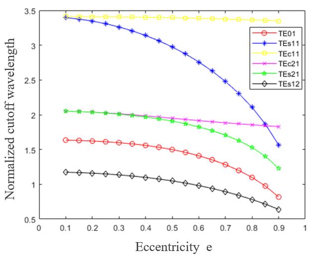
The central frequency point of the elliptical waveguide mode converter designed in this paper is 28 GHz,the long semi-axis is a=16 mm,the long axis is fixed,and the short axis depends on the selection of the eccentricity. Designing an efficient TE01-TE11 elliptic waveguide mode converter requires both improving the TE01-TE11 coupling ability and suppressing spurious mode output.
In the elliptical TE01-TE11 mode converter,the normalized cutoff wavelengths of the main modes are shown in
![]()
Figure 1.The major mode normalized cutoff wavelengths in elliptical waveguides
After determining the bending direction and the main coupling mode of the elliptical waveguide,it is necessary to analyze the stronger spurious modes present in the converter. TEs11 will have stronger coupling with TEc21,thus increasing the spurious mode TEc21 and thus reducing the output power of TEs11 mode;TE01 will have stronger coupling with TEs12 mode,which will reduce the input power of the input mode TE01 and increase the spurious mode TEs12,which affects the conversion of TE01 to TEs11. In addition,there are also TEs21,TMc11, TMs21 and other heterodyne modes.
![]()
Figure 2.The variation law of coupling coefficient with eccentricity
Obviously,the coupling ability of the interaction modes depends on the coupling coefficient and the difference of eigenvalues is defined by the following expression:Q = c/(βm–βn),where c is the coupling coefficient between the modes m and n. βm and βn are the mode phase constants,respectively. As shown in
![]()
Figure 3.The variation law of coupling ability with the eccentricity
After determining the elliptical cross-sectional dimensions,the phase rematching method is introduced into the elliptical waveguide longitudinal contour line[
where
After determining the cross-sectional dimensions and the longitudinal contour line structure of the elliptic waveguide mode converter,the longitudinal structure needs to be optimized in order to improve the conversion efficiency of the elliptic waveguide converter. In this paper,the seven parameters of perturbation amplitude
The values of these seven parameters were obtained by writing a numerical calculation program in MATLAB and optimizing the parameters of the contour line structure as well as the lengths,as shown in
| e3 | |||||||
|---|---|---|---|---|---|---|---|
| 0.112 7 | 0.036 1 | 0.019 2 | 0.15 | 0.003 8 | -0.004 3 | 253.7 mm |
Table 1. The parameter table for particle swarm algorithm optimization
Once the optimized parameters are obtained,the contour line structure of the mode variator can be derived as shown in
![]()
Figure 4.Elliptical waveguide mode converter contour line
In order to make the numerically calculated efficiency more accurate,eight modes are considered in the numerical calculation procedure,respectively TE01,TEs11,TEs12,TEc21,TEs21,TM01,TMc11,TMs21. The efficiency of the TE01-TE11 mode converter is finally calculated to be 99.23%. The numerical simulation of the conversion process of the relative power of the mode converter is shown in
![]()
Figure 5.Numerical simulation process of relative power of each mode of TE01-TE11 mode converter
Modeling and simulation are performed in CST simulation software to further verify the feasibility of the designed elliptic mode converter by analyzing the results after simulation.
The model diagram of the elliptic waveguide TE01-TEs11 mode changer built in CST is shown in
![]()
Figure 6.Elliptical waveguide TE01-TEs11 mode converter model diagram
![]()
Figure 7.Elliptical waveguide TE01-TEs11 mode converter sweep chart
![]()
Figure 8.Elliptical waveguide TE01-TEs11 mode converter profile electric field diagram
In practice,the input and output ports of the cyclotron are usually circular waveguides,so a section of transition waveguide needs to be added to each end of the designed elliptical waveguide TE01-TEs11. The radius of the circular waveguide at the input and output ports of the mode converter designed in this paper is 16 mm;therefore,a section of transition from the circular waveguide TE01 to the elliptical TE01 and a section of transition from the elliptical waveguide TEs11 to the circular waveguide TE11 are required.
Since elliptical waveguides are not completely symmetrical like circular waveguides,it is difficult to design the transition profile,so the current design of the circular to the elliptical waveguide transitions usually uses direct simulation. For the circular waveguide TE01 to the elliptical waveguide TE01 transducer,the simulation is built in CST to obtain the length L1=400 mm that meets the design,and the relative conversion efficiency at the center frequency point is 99.32%. Similarly,the elliptical waveguide TEs11 to the circular waveguide TE11 transducer is modeled in CST,and a transducer length L2=105 mm is obtained in accordance with the design,with a conversion efficiency of 99.88% at the center frequency point.
The overall structure and profile electric field amplitude distribution of the TE01-TE11 mode converter,which has an overall length of L=758.7 mm,were obtained by connecting the designed mode converter and two transition segments together in the CST,as shown in
![]()
Figure 9.Elliptical waveguide TE01-TE11 mode converter overall structure and profile electric field distribution diagram
When designing devices such as mode converters,the power capacity of the device must be considered,because if the power of the mode converter is too small,it will be broken by the electric field in the vacuum,causing the firing phenomenon and thus affecting the service life of the converter.
with the input power
3 Conclusion
In this paper,the elliptical waveguide TE01-TE11 mode converter is designed and studied. The design principle of elliptical waveguide TE01-TEs11 mode converter is analyzed. Meanwhile,the waveguide bending direction is selected according to the normalized cutoff wavelengths at different eccentricity,after that the coupling coefficients and coupling ability of TE01-TEs11 and TEs11-TEc21 are calculated. The appropriate elliptical waveguide cross-sectional dimensions were selected according to the laws of their coupling coefficients and coupling capacities. The serpentine coupling structure is adopted,and a program is written to optimize the waveguide contour line curve parameters,and the simulation is verified in CST,and the simulation results are verified to be consistent with the results calculated by the program. The designed elliptical mode converter is connected with two transitions and simulated and verified in CST. An efficient,compact,high-power,elliptical waveguide TE01-TE11 mode converter with center frequency point at 28 GHz is designed.
References
[2] Keqiang Wang, Tianming Li, Li Hao et al. A broadband TE01–TE 11 mode converter with elliptical section for gyro-TWTs. IEEE Transactions on Microwave Theory and Techniques, 67, 3586-3594(2019).
[5] J. Barker, E. Schamiloglu. High-Power Microwave Sources and Technologies(2001).
[8] Le Xu, Xin-jian Niu. 8mm high power TE01—TM11 mode converter in overmoded waveguide, 487-488(2009).
[10] G. Blanch, M. Abramowitz, I. Stegun. Handbook of Mathematical Functions, 721-750(1964).


Set citation alerts for the article
Please enter your email address

© Copyright 2018-2021 | Chinese Laser Press. All Rights Reserved 沪ICP备15018463号-20