The photonic spin Hall effect (SHE) refers to the transverse spin separation of photons with opposite spin angular momentum, after the beam passes through an optical interface or inhomogeneous medium, manifested as the spin-dependent splitting. It can be considered as an analogue of the SHE in electronic systems: the light’s right-circularly polarized and left-circularly polarized components play the role of the spin-up and spin-down electrons, and the refractive index gradient replaces the electronic potential gradient. Remarkably, the photonic SHE originates from the spin-orbit interaction of the photons and is mainly attributed to two different geometric phases, i.e., the spin-redirection Rytov-Vlasimirskii-Berry in momentum space and the Pancharatnam-Berry phase in Stokes parameter space. The unique properties of the photonic SHE and its powerful ability to manipulate the photon spin, gradually, make it a useful tool in precision metrology, analog optical computing and quantum imaging, etc. In this review, we provide a brief framework to describe the fundamentals and advances of photonic SHE, and give an overview on the emergent applications of this phenomenon in different scenes.
Introduction
The photonic spin Hall effect (SHE)1, 2 is a fundamental optical phenomenon after the beam passes through an optical interface or inhomogeneous medium, which refers to the transverse spin-dependent splitting of photons relative to the geometric optical trajectory. This effect can be regarded as an evolution from the SHE in electronic systems. In 1879, Edwin Hall experimentally discovered that when the electrical current passes through the conductor perpendicular to the magnetic field, the charge carriers disturbed by the Lorentz force form a voltage difference across the conductor3. Such a classical phenomenon was later known as the Hall effect, and a series of Hall effects have also been presented and investigated after its original discovery. For example, the Hall resistance exhibits the quantized features4 since the charge carriers in the conductor are confined to a two-dimensional (2D) system, bringing about the integer quantum Hall effect and the fractional quantum Hall effect5-7. The discoverers of the two quantum Hall effects, i.e., Klitzing and Tsui won the Nobel Prize in physics for their outstanding scientific contributions.
In addition to the electric charge, electrons have another degree of freedom called spin, which corresponds to the SHE originating from the spin-orbit interaction (SOI)8-12. The spin-up and spin-down electrons in the current-carrying sample separate from each other, and manifest themselves as spin accumulation at the lateral boundary of the sample, even though without an applied magnetic field. Since the initial experimental observation by Awschalom et al. in 20049, the SHE has become a hot spot in the field of condensed matter physics. Note that the SHE can occur even in non-magnetic materials, which is strongly related to the spin of the electrons and thus shows differences from previous Hall effects. More importantly, both the spin and charge of electrons have the ability to store and transmit information as well, and the current in the SHE almost produces no energy loss, which can greatly reduce the heat loss in materials and contributes to the spin-based electronic components13-15. Moreover, the anomalous Hall16-18, quantum anomalous Hall19-22, quantum spin Hall23-28, as well as valley Hall effects29-31 have also been successively discovered, forming a large family of Hall effects and attracting constant attention in fundamentals and applications.
Since a series of Hall effects specifically for electrons have been proved, will photons as a neutral particle with spin property also produce an interesting effect similar to the SHE in electronic systems? The answer is undoubtedly yes, and the corresponding phenomenon is called the photonic SHE. In 2004, Bliokh et al. introduced a geometric Berry phase to explain topological spin-dependent splitting of photons in inhomogeneous isotropic media and connected it to the anomalous Hall effect of electrons32, 33. In the same year, Onoda et al., from the perspective of the geometric Berry phase and angular momentum conservation principle, clearly proposed the presence of the photonic SHE after the light beam reflection and refraction at the media interface1. It is demonstrated that the photonic SHE can be regarded as an analogue of the SHE in electronic systems, where the light’s right-circularly polarized (RCP) and left-circularly polarized (LCP) components play the role of spin-up and spin-down electrons, and the refractive index gradient replaces the electric field, respectively. Meanwhile, the photons with opposite spin angular momentum (SAM) undergo a spin-dependent splitting in the direction perpendicular to the incident plane. Subsequently, Bliokh et al. further proposed a complete theory to calculate and describe the photonic SHE2, 34. They pointed out that the total momentum conservation of all photons must be taken into account for the derivation of correct photonic SHE expressions, instead of the angular momentum conservation of a single photon. Therefore, the polarization vectors of each angular spectrum acquire different geometric phases for the beam propagation in momentum space, and the phase gradient is manifested as the spin Hall shift in real space.
In fact, the photonic SHE originates from the SOI of light35-37, and can mainly be attributed to the optical angular momentum38 and two geometric phases, i.e., the spin-redirection Rytov-Vlasimirskii-Berry (RVB) phase associated with the propagation direction of the wave vector, and the Pancharatnam-Berry (PB) phase related to the polarization manipulation of light39-44. The spin Hall shift is very tiny and almost on the scale of sub-wavelength due to the weak SOI, which poses a great hindrance to its direct measurement. It was not until 2008 that Hosten and Kwiat first experimentally observed the photonic SHE45 at the air-glass interface by weak measurements, and verified the theory previously proposed by Bliokh et al. Similar to the electronic SHE, the photonic SHE serves as the carrier of information and energy propagation, which shows great advantages in energy storage, measurement, operation and other aspects. Meanwhile, the spin Hall shift observed by weak measurements exhibits a high sensitivity to the physical parameters and thus presents a powerful influence in the characterization of tiny variables. Taken together, the development of the photonic SHE is believed to contribute the spin-based optical devices and yield a new topic related to spin photonics, even produce some emergent applications in extensive fields.
By the way, there exists an effect with a similar origin to the photonic SHE, called the optical SHE46. Despite the spin separation in both the effects, their exact configurations are not the same. The photonic SHE manifests itself as the spin-dependent splitting of photons, which is implied by the conservation of angular momentum of light. However, the optical SHE deals with the optically generated spin currents of exciton-polaritons in semiconductor microcavities, which describes the spin separation of electrons induced by optical methods in nature. In 2005, Leyder et al. observed the optical SHE for the first time in a high-quality GaAs/AlGaAs quantum microcavity47. The accumulation direction of the spin currents in the microcavity can be changed by rotating the polarization plane of the exciting light. Subsequently, a series of explorations have been carried out on the optical SHE and its related phenomena. For instance, the non-linear optical SHE48, the tunable optical SHE in liquid crystal cavities49, the extensions of optical SHE to the valley degree of freedom31, and the measurement of the Berry curvature and the anomalous Hall effect of photons50. The study of optical SHE provides a convenient and efficient way to generate and probe the electron spin flow, which bridges the SHE between electronic and optical systems and is therefore valuable in the field of optoelectronics.
In this review, we aim to provide a brief framework for the discussion of the fundamentals and applications of photonic SHE. Firstly, we describe the fundamental concepts of photonic SHE from the perspective of SOI underpinned by optical angular momentum and geometric phase. Secondly, we introduce the advances of photonic SHE induced by two geometric Berry phases in different physical systems. Finally, we summarize the emergent applications of this effect in recent years such as precision metrology, analog optical computing and quantum imaging for edge detection.
Spin-orbit interaction: A fundamental description of the photonic SHE
The description of photonic SHE is necessary to discuss its physical origin. Light is a particle with wave-particle duality51, so that the photons possess spin angular momentum (SAM) and orbital angular momentum (OAM) like other classical particles38, 51-55. The universal view suggests that the photonic SHE originates from the SOI of light, which manifests as the mutual influence and interplay between the polarization and the trajectory of light36, 37. The components of the circularly polarized light with opposite chirality carry different geometric phases correspondingly, bringing about the spin separation of light beam and resulting in the photonic SHE. Remarkably, the SOI of light is closely related to the optical angular momentum and the two geometric Berry phases (i.e., the RVB phase and the PB phase). We next introduce the fundamentals of the spin-orbit interaction as well as the optical angular momentum and the geometric phase.
The optical angular momentum
The optical angular momentum can influence the polarization and phase of light, distinguishing the photons significantly from classical particles such as electrons. In 1909, Poynting noted that the SAM of photons is related to the polarization of light56. Beth et al. in 1936 verified that the RCP and LCP photons carry the SAM57:
where
is consistent with the direction of beam propagation and mainly depends on the handedness
(
for RCP and
for LCP).
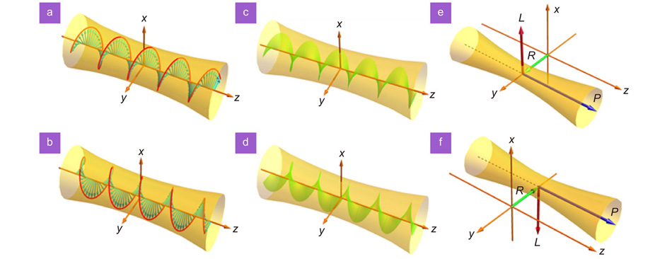
represents the momentum. In quantum mechanics, the RCP and LCP components correspond to the two spin states of the photons, as the electric and magnetic fields rotate around the wave vector direction [Fig. 1(a) and 1(b)]. Each photon for opposite states carries a SAM of
and
correspondingly, where
is the reduced Planck constant.
Figure 1.The spin angular momentum (SAM) and the orbit angular momentum (OAM) of paraxial beams. The transient electric field vector of circularly polarized beam brings the SAM of (a)
and (b)
; the intrinsic OAM in a vortex beam with topological charges of (c) l = +1 and (d) l = −1; the extrinsic OAM occurs in x-direction when the beam undergoes a (e) positive or (f) negative shift in y-direction.
In 1992, Allen et al. revealed that the photons also have OAM58. Many applications based on OAM have subsequently become the forefront of optics, and have been widely studied and applied in particle control, image processing, microimaging, quantum imaging and other aspects53. There are two forms of OAM, namely, the intrinsic OAM (IOAM) only related to the optical vortices, and the external OAM (EOAM) associated with the beam propagation trajectory52, 59. The IOAM derives from the fundamental spin properties of the Maxwell’s equations, which can be written as
Remarkably, the IOAM is widespread in the light beam with a helical phase factor
, and each photon in such beam carries an OAM of
[Fig. 1(c) and 1(d)]. Here,
is an integer representing the quantum number of OAM also called topological charge, and
denotes the azimuthal angle. Notably, the helical phase is embodied as a rotational symmetric structure. However, when this rotation symmetry is broken in the case of beam propagating at a distance from the coordinate origin, the centroid shift of beam appears resulting in the conversion from IOAM to EOAM. Such phenomenon is regarded as an analogy to the mechanical angular momentum of classical particles, usually described by the cross-product of the transverse position of beam centroid
and its momentum
[Fig. 1(e) and 1(f)]36:
The mutual influence and conversion between the SAM and the IOAM or EOAM contribute to the SOI of light. Firstly, the interaction between SAM and IOAM results in the spin-to-orbital angular momentum conversions and acquires the helicity-dependent optical vortices60, 61. This interaction usually occurs in cylindrical or spherical symmetric systems, mainly manifested as spin-dependent effects and anisotropic structure-induced phenomena in focused or scattered light fields. Here, a typical example is non-paraxial beams focused by high numerical aperture lenses or scattered by tiny particles, where the SOI strongly impacts the light field distribution62-64. In 2010, Rodríguez-Herrera et al. presented a high-numerical-aperture (high-NA) microscopy (acts as a “lens-scatterer-lens” system), which consists of a high-NA focusing lens (for the incoming paraxial light), a scattering specimen in the sensitive focal field and a high-NA lens (capturing the scattered radiation in the far field)64. Using such a system, the light scattered in the focus of the high-NA objective by a nanoparticle appears angular momentum conversion, and the strong SOI of light is produced, which translates fine information about the specimen to the polarization distribution of the outgoing paraxial field. Therefore, the fine information about the scattering particle can be retrieved by the changes in the far-field polarization, which contributes to a far-field optical nanoprobing technique based on the SOI of light. Secondly, the coupling between SAM and EOAM produces a series of helicity-dependent spin Hall effects manifested as beam shifts in position or momentum space. In essence, one of the most typical cases of this coupling is the beam refraction (or reflection) at the air-glass interface, as commonly described by Snell’s law and the Fresnel equations36, 45. Also, this coupling possesses some important effects in special systems such as waveguide structure and surface plasmon metasurfaces65, 66. For example, the internal SAM and OAM in the flow of light controlled with nanophotonic waveguides get coupled due to the strong transverse confinement of the guided photons. O’Connor et al. in 2014 applied this coupling to realize a chiral waveguide coupler by breaking the mirror symmetry of the light scattering with a gold nanoparticle, on the surface of a nanophotonic waveguide66. Besides, the orbit-orbit interaction between the IOAM and EOAM drives the orbit Hall effects represented as the vortex-dependent beam shifts67, 68. We focus on the SOI of light between SAM and OAM, and discuss the resulting photonic SHE in combination with the perspective of the geometric phase in this review. The orbital Hall effects are analogous to the spin Hall effects considered here and are therefore no longer analyzed.
The geometric Berry phase: spin-redirection RVB phase and PB phase
The geometric Berry phase39-44, as a typical manifestation of the interaction between the SAM and OAM, initiates a series of phenomena related to the photonic SHE. It is induced by the geometrical properties of the Hamiltonian parameter space69-71, and was extended as a fundamental notion of almost all branches of physics gradually. In 1984, Berry proved that the cyclic and adiabatic evolution of the quantum states in the parameter space brings about geometric phases40. Inspired by this, the optical analogies of the Berry phase in quantum mechanics were restudied72, 73.
In fact, the geometric phase in optics essentially originates from the interaction between intrinsic angular momentum and rotations of coordinates. Suppose a vector moves in parallel along a closed loop in a three-dimensional (3D) curved space for a period, it will return to the origin in position but rotates at a slight angle in direction compared to the starting point. This behavior is called the overall change of vector. Meanwhile, the vectors do not rotate relative to the normal of curved surface during the parallel variation along the closed loop, so that no local change of vector appears. Such a trend of the vector without local change but with the overall change is actually the geometric phenomenon on the 3D curved space, and the overall change is closely related to the geometric path. Notably, the 3D space here is not limited to the real curved surface of the position space or the momentum space, but can also be the surface of the parameter space. Conversely, if such a parallel movement of the vector occurs in the flat space, no rotation appears when the vector returns to the origin.
Two common curved spaces in optical systems can be applied to describe the two geometric phases of spin-redirection RVB phase and PB phase, namely, the momentum space and the Stokes parameter space. We next discuss the two curved spaces and describe how they interpret the geometric phases in optics. When the light reflects at the optical interface or passes through the waveguide, its propagation trajectory changes, revealing the geometric parallel transport of the wave vector on the curved surface of sphere in the momentum space [Fig. 2(a)]. The polarization of the plane-wave in vacuum is always orthogonal to its wave vector
, which means that the polarization depends on the wave vector and is tangent to the directional
-sphere in the wave vector space36. The polarization vector (i.e., the unit electric field vector to characterize the propagation of circularly polarized waves) does not rotate locally but inevitably has the overall change on the curved space, maps to the adiabatic evolution, thus inducing geometric phases in circularly polarized waves. In the laboratory coordinate frame, converting the circular polarization
to the spherical coordinates
, the geometric phase can be obtained by the corresponding Berry connection
and Berry curvature
74:
Figure 2.Geometric phases and their generation in three-dimensional curved space. (a) The non-trivial parallel transports of wave vector appear in the three-dimensional momentum space to provide geometric phases. (b) Propagation of the fiber axis along a curvilinear trajectory. (c) The non-trivial parallel transport of Stokes vector in three-dimensional Stokes space. (d) The geometric phase gradient is acquired when the circularly polarized beam passes through a nonuniform birefringence wave plate with a locally varying optical axis.
and here,
and
play the role of the effective “vector potential” and the “magnetic field” in the momentum space, respectively. The polarization vector
moves in parallel along circuit C in the parameter space, and then returns to the initial state for an additional geometric phase:
For the rotating of a certain angle
, the RCP and LCP waves acquire opposite geometric phases
. For the whole loop, subtracting the
rotation of the spherical
coordinates, and then the global geometric phase for the solid angle Ω enclosed by the loop can be given by:
We can understand such adiabatic evolution by considering the rotation of polarization plane in the single turn of a helically wound optical fiber, where a single mode of axial wave vector propagates [Fig. 2(b)]. The trajectory of the fiber axis in
-space is a small circle on the sphere of wave vectors, and the circle closes itself due to the start and finish of the fiber being parallel. The solid angle that is subtended by this small circle at the center of the sphere gives the phase difference75.
Another curved space called the Stokes sphere is used to describe the evolution of the polarization state in the Stokes parameter space. The parallel transport of the vector over the sphere reveals the inevitable rotation between the transported vector and the global spherical coordinates, inducing geometric phases in circularly polarized waves [Fig. 2(c)]. A typical example is the circular polarized beam passing through a nonuniform birefringence wave plate [Fig. 2(d)]. Based on the evolution of polarization state
in the Stokes parameter space, the geometric phase can be given by Berry connection
and Berry curvature
36:
In Berry’s fundamental framework, the variation of polarization state
brings out an extra geometric phase:
where
in spherical coordinate, and Eq. (10) can be further described as
Therefore, the Berry connection and the Berry curvature are similarly expressed in both momentum and Stokes parameter spaces, and the geometric phase can be simply determined as half of the solid angle.
The above discussions focus on the parallel transport of the vector along a closed loop in curved space. In fact, the transmission route of vector in curved space is mostly not a closed loop, such as the reflection, refraction and focus of the beam on the interfaces. Adopting the momentum space to describe these behaviors, the evolution trajectory of the wave vector is unclosed. This interesting phenomenon can be analyzed for the geometric phase by the global rotation of the polarization, as a result of the parallel transport of the wave vector in the momentum space.
The spin-redirection RVB phase was initially studied by Rytov and Vladimirskii and progressively supplemented with the studies76, 77. The spin-redirection RVB phase is attributed to the evolution of the beam transport. Consider the angular spectral theory of plane waves, a paraxial beam can be regarded as a superposition of many plane waves (i.e., angular spectral components), and each component with tiny deviations in direction. When such a paraxial beam partially is reflected or refracted at the optical interface (i.e., the propagation trajectory changes), the polarization vectors of angular spectral components undergo different rotations to satisfy the transverse properties of the electromagnetic field. As a result, different spin-redirection phases are obtained to form a geometric phase gradient accompanied by the appearance of SOI, which manifests as a transverse centroid shift of the photonic SHE in position space:
The phase gradient
depends on the transverse wave vector component
, and
is a coefficient associated with the optical interface parameters. In a word, the centroid shifts of photonic SHE in real space originates from the
-space spin-redirection RVB phase gradient.
The angular momentum of the photon actually consists of a superposition of the SAM and the OAM, so that the transverse spin Hall shifts can also be analyzed by considering conservation of total angular momentum in the normal direction. The SAM in normal direction changes when a uniform linearly polarized beam is reflected or refracted, thus its RCP and LCP components must split in the opposite direction, i.e., form spin Hall shift to yield a non-zero EOAM (i.e., acquire the OAM in the opposite direction of the normal SAM) and compensate itself. We then derive the spin Hall shift in real space further, which can be written as37
Obviously,
in the real space originates from spin-redirection RVB phase gradient in the
-space and is a constant of
, which is closely related to the Fresnel coefficients and configuration parameters of optical interfaces. Therefore, the photonic SHE can also be manipulated by adjusting the physical parameters.
The PB phase is another Berry phase related to the polarization manipulation of light. In 1956, Pancharatnam first discovered the PB phase in the light field39, and Berry re-examined and promoted it in 198778. As shown in Fig. 2(d), a spatially varying PB phase occurs when the beam passes through a nonuniform birefringence wave plate with a locally varying optical axis, such as the sub-wavelength polarization grating79, 80, q plate81, and metasurfaces82-86. Importantly, this phase depends only on the optical axis orientation of the wave plate87, 88. For an incident beam with circular polarization, the transformation process ignoring the absorption and loss of the wave plate, can be described by Jones matrix as
here,
is the phase retardation of the wave plate.
is the optical axis orientation with
indicating an integer or half-integer and
representing the azimuthal angle.
denotes the origin orientation of the optical axis at
. Combined with Eq. (4), some of the incident photons reverse their chirality and can be imprinted by an additional PB phase
while the others
remain unchanged. This process is accompanied by a conversion of the SAM to IOAM, where the PB phase gradient manifested as the spin Hall shift in the momentum space89, 90:
For the circularly polarized incident beams with opposite chirality, the reverse phase gradients are acquired. Converting the coordinate from the momentum space to the real space, the momentum shift will result in a real space spin Hall shift
which is associated with beam propagation distance
.
So far, we have made a fundamental description of photon SHE based on the viewpoint of the optical angular momentum and geometric Berry phase. In brief, the photonic SHE originates from the SOI of light, formed by the mutual influence and interplay between the polarization and the trajectory (i.e., the SAM and the OAM) of light. When the propagation trajectory of paraxial beam changes, the polarization vector of each angular spectrum component rotates in momentum space (
space) to acquire different spin-redirection RVB phases, resulting in the redistribution of light intensity. Then, a geometric phase gradient is obtained, which manifests as the spin-dependent splitting of the beam centroids in real space. Nevertheless, when the paraxial beam passes through an inhomogeneous anisotropic medium, a spatially varying PB phase can be obtained in real space and lead to a spin-dependent momentum shift. Significantly, the beam shift induced by the spin-redirection RVB phase is very tiny and appears in the position space, which can be amplified by weak measurements or multiple reflections, while the one induced by the PB phase increases with the beam propagation and thus facilitates direct measurement. The unique properties of beam shifts and their potential applications constitute a significant difference between the photonic SHE induced by the two geometric Berry phases and attract wide attention.
Recent advances in photonic spin Hall effect
Photonic SHE induced by the spin-redirection RVB phase
The reflection and refraction of plane waves at the optical interfaces are fundamental processes in optics and can be described by Snell’s law and the Fresnel formula. However, the propagation evolution of finite-width paraxial beam can be regarded as a superposition of many plane waves with tiny differences in propagation direction upon optical interfaces, and does not exactly cater to the geometric optical predictions. In this case, a geometric phase gradient is formed and manifested as the beam centroid shifts relative to the geometric optical direction, and the photonic SHE is one of the representatives. The photonic SHE induced by the spin-redirection RVB phase is generally believed to be a spin-dependent splitting perpendicular to the incident plane36, 37, originated from the interaction between the SAM and the EOAM after the paraxial beam passes through media interfaces [Fig. 3(a)]. The parallel transport of wave vectors in the momentum space will inevitably result in the polarization rotation, and these rotations corresponding to different angular spectrum components exhibit slight differences [Fig. 3(b)]. Besides, geometric phase gradients can also bring about the in-plane Goos-H
nchen (GH) shift91-95 and the out-of-plane Imbert-Fedorov (IF) shift perpendicular to the incident plane96-99. The GH shift is a result of the spatial dispersion of beam reflection and transmission coefficients and the interference of the angular spectrum components, which was theoretically proposed by Goos and H
nchen91 and then experimentally demonstrated by Artman92. The concept of the IF shift was first presented by Fedorov96 and then probed by Imbert97 in total internal reflection. Both the two shifts have attracted wide attention and become hot issues in optics. Note that the IF shift and the spin Hall shift are formulated in a completely different way, although both of them can be attributed to the SOI of light and are associated with the spin-redirection RVB phase. The IF effect takes into account the overall centroid shift after the reflection or refraction of the beam with RCP or LCP at the optical interface, and the helicity of the beam directly corresponds to the SAM of the photons. Differently, the photon SHE considers the incident linearly polarized beam as a superposition of the RCP and LCP components, and the spin-dependent splitting of the two components occurs after beam reflection or refraction due to the electromagnetic properties of the interface.
Figure 3.Photonic SHE induced by the spin-redirection RVB phase at an optical interface. (a) The linearly polarized beam splits into the RCP and the LCP components after reflecting from an optical interface, manifested as the spin-dependent splitting. (b) The beam reflection can be regarded as the parallel transport of wave vectors in the momentum space, resulting in the polarization rotation.
In recent decades, the photonic SHE has been investigated in series of interfaces and systems, such as the air-glass interface and 2D atomic crystals. In 2008, Hosten et al. first observed the transverse shift of photonic SHE resulting from beam refraction at the air-glass interface using weak measurement45. The maximum amplified shift they obtained is about 76 nm with a detection accuracy of 0.1 nm. In 2009, Qin et al. confirmed in the same way that the photonic SHE also exists in the process of beam reflection at the air-glass interface100. Consider the interplay between the SOI of light and the GH effect of beam reflection, an in-plane spin separation of light distinguished from the GH shift and the spin-Hall shift, has also been experimentally observed101. Two years later, Bliokh et al. demonstrated that the accumulation of the spin Hall shift can be achieved along a smooth helical trajectory by considering the multiple total internal reflection of light in a circular glass, thus enabling direct detection of the beam shifts without weak measurements74. Kong et al. developed a modified calculation theory of the photonic SHE for the light reflection at the air-glass interface, and observed the spin-dependent shifts near the Brewster angle using weak measurements102.
The photonic SHE has also been imaged in semiconductor GaAs via an optical pump-probe technology103. Ménard et al. observed the SHE of a nonnormally incident probe light, through the variety of pump-induced changes to a material’s optical properties. The splitting of photons (with different helicities) couples to different spins of electrons in the GaAs, as a result of the transfer of SAM from photons to electrons. This offers a pathway to detect the carrier density of the spin electrons by measuring the photonic SHE, bridging the photonic SHE to condensed matter physics. In metamaterials, Yin et al. in 2013 obtained a giant spin Hall shift by using an inhomogeneous plasmonic metasurface with a rapidly varying phase discontinuity104. This metasurface is combined by a fixed arrangement of cells of different geometries, and the dynamic phase gradient along the surface guarantees a deflection of the beam even at normal incidence. Note that although the spin Hall shift observed here occurs in beam refraction at the air-metasurface interface, the essence of its dynamic geometric phase is not the PB phase gradient but the spin redirection phase due to the unchanged local optical axis orientation. By the way, the explorations have also been carried out on the active manipulation of photonic SHE by external fields such as polarization and strain105, 106. These studies laid a solid foundation for the acquisition of giant photonic SHE.
Luo et al. have also been engaging in the investigation of photonic SHE and made some systematic results in the past decade107-121. Some classical studies generally believe that the photon tunneling is a 2D process (namely, the tunneling only occurs in the incidence plane)122, 123, but the total angular momentum is not conserved in the 2D frustrated total internal reflection. Luo et al. resolved the breakdown of angular momentum conservation in 2D photon tunneling by considering the photonic SHE108. It was found that the spin components of linearly polarized beam produce transverse splitting perpendicular to the incident interface after tunneling through the prism-air-prism barrier. Meanwhile, the transverse splitting is governed by the total momentum conservation law and can be enhanced evidently via photon tunneling, which in turn shows that the photon tunneling is actually a 3D process. Some attempts were also made to enhance the photonic SHE, where the spin Hall shifts can reach up to several wavelength orders (~ 3200 nm) near the Brewster angle at the air-glass interface, about 50 times the previously reported spin-dependent splitting of beam refraction110. Meanwhile, the study of photonic SHE has been developed in chiral materials107, multilayer nanostructures109, nanometal thin films111, 2D atomic crystals112, 114, 117, 118, 120, 121, and novel topological materials113, 116, 119, etc. It is shown that the spin Hall shift is very sensitive to the optical properties of the interface, so the manipulation of photonic SHE can be realized by adjusting the interface with appropriate optical parameters, such as enhancing or suppressing the beam shift and switching the direction of spin accumulation. In turn, the photonic SHE is expected to serve as a probe to measure the thickness of metal and magnetic nanofilms, even to determine physical parameters of atomically thin 2D material and other structures.
Notably, the spin-dependent splitting in the above studies is generally tiny spatial spin Hall shift induced by the spin-redirection RVB phase, which is sometimes accompanied by the occurrence of a transverse angular shift115. Although this angular shift is also a momentum shift, it is completely different from the momentum shift induced by the PB phase, because it belongs to the diffraction of beam propagation that is numerically inversely proportional to the beam waist and increases with the propagation distance of beam.
Photonic SHE induced by the PB phase
In optics, the PB phase is closely related to the manipulation of the polarization state of light. When the beam passes through a birefringence wave plate, the PB phase can be obtained by generating the dynamical phase from the optical path difference in addition to the orientation of the optical axis82, 87, 88. Assume that the wave plate has a space-variant optical axis orientation, it can endow the beam with a spatially varying PB phase to form a PB phase gradient, which manifests as a spin Hall momentum shift (i.e., angular shift in momentum space) since the PB phase gradient is spin-dependent in nature. The investigation of PB phase opens the way for the study of the photonic SHE and brings opportunities for the development of emerging spin photonic devices.
Studies and extensive explorations have been made in terms of the observation and manipulation of photonic SHE induced by PB phase for several years. Shitrit et al. in 2011 observed the one-dimensional (1D) spin Hall momentum shift on two different constructed plasmonic chains experimentally124. The photonic SHE in the two different structures, i.e., the isotropic chain or the local anisotropic chain, respectively, results from the interaction between the photon spin and the curvature path, and the coupling between the spin photon and the local anisotropy. In particular, because the gradual evolution of local optical axis orientation, the chirality of circularly polarized beam reverses after passing through the second structure. Consequently, a locally varying PB phase gradient is formed, which manifests itself as a spin-dependent momentum shift. In this process, the SAM of light is partially converted into the IOAM.
Subsequent studies show that the photonic SHE can be manipulated by regulating the spatially varying PB phase125. When a polarized beam is normal incident into a wave plate with the local optical axis orientation varying along the azimuthal direction, its PB phase also changes in the azimuth direction, yielding a spin-dependent geometric phase gradient and ultimately as an azimuth photonic SHE with rotational symmetry. Controlling the PB phase based on such principles enables the appropriate manipulation of the spin-dependent splitting. Furthermore, it is worth noting that when the PB phase gradient appears in the radial direction, the two spin components of the beam will focus and defocus, respectively, and the spin Hall momentum shift occurs in the radial direction80.
It is worth noting that the metasurfaces regarded as emerging materials artificially fabricated to meet various electromagnetic properties, which also provide great degrees of freedom for creating various refractive index gradients as well as manipulating SOI of light and photonic SHE89, 126, 127. In 2015, a giant photonic SHE was presented with nearly 100% efficiency at metasurfaces (with deep-subwavelength thicknesses)127. To get the 100% efficiency, the metasurface samples should avoid multimode operation, and their building blocks must be either perfectly transparent or perfectly reflective. The authors of ref.127 established a general model for this purpose based on rigorous Jones matrix analysis, and then fabricated two realistic microwave samples with distinct symmetry properties. It is found that both samples show very high efficiencies for photonic SHE within a broad frequency band. Meanwhile, a giant spin Hall momentum shift was obtained in a structured metasurface with spatially varying birefringence89. As shown in Fig. 4(a) and 4(b), the metasurface is fabricated of spatially varying nanogrooves written by a femtosecond laser in a focused silica sample, whose characteristic dimension of the structure is much smaller than the operational wavelength. Under intense laser irradiation, the uniform glass decompositions into porous glass, and its refractive index depends on the laser intensity. Therefore, the periodic variation of the laser intensity can be applied to modulate the glass refractive index to form grating-like nanostructures, yielding a birefringence in the isotropic glass sample. The orientation of locally varying optical axes, i.e., fast and slow axis, is perpendicular and parallel to the grooves. Therefore, such a metasurface can create a coordinate-dependent PB phase that, results in an SHE with a spin-dependent splitting in momentum space, much larger than the real-space spin Hall shifts induced by spin-redirection RVB phase. The spin-dependent splitting and the rotational symmetry of its spin accumulation can be determined directly by measuring the Stokes parameter
without weak measurements [Fig. 4(c) and 4(d)]. Based on the features of metasurfaces, some phase elements composed by metasurfaces for instance the optical lenses have been proposed, which updates the degree of freedom for light manipulation128-131.
Figure 4.Schematic and experimental illustration of photonic SHE induced by the PB phase in a metasurface. (a) The conservation of the spin states as a circularly polarized beam passes through a structured metasurface with a spin-dependent PB phase gradient
ΦG. The green arrows through the metasurface and the varying short lines marked on the metasurface represent the wave vectors and the local optical axis orientation, respectively. For incidence of right-circularly polarized (RCP, indicated by σ+ in red) light or left-circularly polarized (LCP, indicated by σ– in blue) light, the metasurface produces the opposite
ΦG and acquires the opposite spin-dependent momentum shifts. The corresponding polarization evolution is presented on the Poincaré sphere, where the trajectories (A, B) and (C, D) represent the initial spin states conservation in metamaterials with different local optical axes. (b) Detailed photograph and geometry of the metasurface with local optical axis (slow axis) over one period (20 mm). In such a metasurface, the mapping relationship between the momentum shift Δk and the induced real-space shift Δx is given. After the linearly polarized beam passes through the metasurface with rotation rate Ω = π/20 rad μm−1, the calculated (Cal.) and experimental (Exp.) results of spin-dependent real-space shift can be obtained in (c), and a charge-coupled device records the light intensity and the corresponding S3 parameter in (d). Figure reproduced with permission from ref.89, under a Creative Commons Attribution-NonCommercial-NoDerivs 3.0 Unported License.
The rotational symmetry breaking of the PB phase elements can also lead to a spin-dependent momentum shift44, 132, 133. Bliokh et al. proposed a spin symmetry breaking effect in plasmonic nanoscale structures in 2008, where a spin-dependent vortex mode with a spiral geometric phase is produced (induced by the SOI) by using a spiral plasmonic microcavity44. Note that the conventional rotational symmetry breaking is achieved by scrubbing part of miniatures of the metasurface, so that the remaining part can still deflect the beam but the wave vectors still cannot be interlaced after propagation. Several relevant alternative approaches have been proposed in recent years. For example, to break the rotational symmetry by shifting the incident beam from the central optical axis of the metasurface132. Under such a system, a phenomenon of spin-dependent splitting arises, which can be manipulated by the rotation rate of the local optical axes. Ling et al. reported the realization of tunable spin-dependent splitting in the intrinsic photonic SHE by breaking the rotational symmetry of a cylindrical vector beam133. In their opinion, the intrinsic vortex phases carried by the two spin components is analogous to the geometric PB phase. Such phases are no longer continuous in the azimuthal direction and result in the observation of spin accumulation at the opposite edge of the vector beam, manifested as the intrinsic photonic SHE. The spin-dependent splitting and the spin accumulation directions, respectively, can be enhanced and switched by regulating the topological charge of the beam.
Quantum weak measurement of photonic SHE
Quantum weak measurement
The photonic SHE is a very slight physical phenomenon, and the spin Hall shifts at optical interfaces are usually with the scale of subwavelength which cannot be directly detected by instruments such as position sensor. The introduction of weak measurement technique45, 134 provides the possibility to measure the spin Hall shift, thus greatly stimulates interest in investigating the photonic SHE at different media interfaces, enabling the application of quantum weak measurements in optical systems. We will present the proposal and development of quantum weak measurements as well as their role in the detection of photonic SHE in the following.
The concept of weak measurement was originally proposed by Aharonov, Albert, and Vaidman (AAV) in 1988134. They introduced the concepts of pre-selection and post-selection states based on the existing strong measurements, and constitute a new weak measurement system. Specifically, such a system was initially used to detect particle spins. Unlike traditional methods that strongly interfere with a quantum measurement system, quantum weak measurements do not significantly perturb the system during the measurements. Assuming that the spin particle is measured at an initial state, the probe of the detection is only weakly coupled to the observable quantity of the measured particle, so that the particle state can be detected without collapsing its quantum state. Subsequently, the particle is post-selected through the final strong magnetic field, and then the measurement system after the weak coupling can be projected onto a quantum state nearly orthogonal to the initial state. Combining the processes of pre-selection, weak coupling and post-selection, we can obtain the results far larger than the eigenvalues. The measurement result here, generally called the weak value, is given by45
where
denotes the pre-selection state,
represents the post-selection state, and
is the observable quantity of the system. When the pre-selection state is closely orthogonal to the post-selection state, the denominator of Eq. (17) approaches null, and then the weak value eventually becomes quite large. Therefore, by using the weak measurements, the significant improvement of precision and sensitivity can be achieved during the parameter measurement. In 1997, Ritchie et al. replaced AAV’s particle experiment by an optical method to first implement the measurement of weak value, which further enables the weak measurement gradually into a powerful tool for precision metrology 135.
Note that according to the fundamental assumptions of quantum mechanics, each isolated quantum system has a Hilbert space associated with it, and such system is entirely described by a unit vector of system state space136. Meanwhile, the observable quantity of the system such as the coordinates and momentum of the particles, can be described by the self-adjoint operator on the Hilbert space. Therefore, the observable quantity
in Eq. (17) is a Hilbert space of a two-level system, which represents the polarization in optics. At this time, we make the two mutually orthogonal base vectors be replaced by
and
, i.e., the RCP and the LCP states. Therefore, the pre- and post-selection states of weak measurement systems can be regarded as137
and here, we have
and
, which directly represent the pre-selection polarization state. For example,
the horizontal linear polarization
and
, the vertical linear polarization
. Besides,
and
are the slight deviation angle relative to state
orthogonal to
, also called as the post-selection angle or the amplified angle.
Substituting Eq. (18) and Eq. (19) into Eq. (17), the weak value can be obtained as a special complex number, whose real and imaginary parts are given by
where
denotes the probability of the post-selection on
. The two amplified angles
and
bring about the real and imaginary parts of the weak values, respectively. For example, in the case of
, we have
and
, and then the weak value turns out to be purely imaginary with
converting the real-space shift to a momentum one. The varying angle
promotes the change of azimuth angle of
. In the case of
, we have
and
, so that the weak value turns to be a purely real value with
, and the variation of angle
can induce the state
switching back and forth between linear, elliptic, and circular polarized states.
In addition, due to the free propagation of wave function, a process of transmission amplification should be considered in weak measurements of the momentum-space spin Hall shift. At any given plane, the enlargement factor can be described as
where
is the Rayleigh distance. After the entire weak measurements, the total amplification factor is obtained:
Except for the exploration on the amplification effect of the real and imaginary parts of the weak values, Jozsa discussed the physical significance of the weak values in the quantum measurements in 2007138. It is demonstrated that both the real and imaginary parts can influence the measurement pointer, where the real part corresponds to the shift of pointer in position space and the imaginary part maps to the momentum space. The particular nature of weak values makes extraordinary applications of weak measurement in various fields. For example, the detection of tiny signals139 and the direct measurement of the quantum wave functions140.
Weak measurement of photonic SHE
Weak measurements of the RVB phase-induced photonic SHE
The research on the photonic SHE was mostly in the theoretical stage at its initial proposal, and later been experimentally proved and popularized. In 2008, Hosten and Kwiat first observed the spin-dependent splitting in photonic SHE by weak experiments45. The pioneering experiment focuses on the beam refraction at an air-glass interface [Fig. 5(a)], which provides an important reference for later detection of the photonic SHE at various interfaces. The optical version of weak measurements was performed in three steps: pre-selection, weak coupling and post-selection, where the corresponding experimental installation is shown in Fig. 5(b). The Gaussian beam generated by the He-Ne laser (
linearly polarized beam at wavelength
) acts as the incident light source, and then passes through the combination of a half-wave plate HWP, a short focus lens L1 (effective focal lengths
), and a Glan laser polarizer P1 to obtain the pre-selected state. Then, the transmitted beam splits into its RCP and LCP components (i.e., spin-dependent splitting of photonic SHE appears) upon refraction at the angular prism VAP (BK7 glass with refractive index
at
). This provides a weak coupling between the meter (the beam transverse spatial distribution) and the observable (operator
with eigenstates
and
). Next, Hosten et al. induce the second Glan laser polarizer P2 which is nearly orthogonal to P1 to post-select the beam. Finally, they add the second lens L2 to form a confocal cavity with L1 to collimate the light, so that the output signal can be captured by the position sensor PS. As shown in Fig. 5(c), the tiny spin Hall shift can be amplified to about 76 nm.
Figure 5.Weak measurements of photonic SHE after beam refraction at an air-glass interface. (a) The RCP and LCP components of a wave packet experience opposite transverse shifts after refraction on an air-glass interface. (b) Experimental setup for observing and amplifying the photonic SHE with incident wavelength of 633 nm. Three main steps in weak measurements should be considered: pre-selection, weak interaction and post-selection. The incident beam passes through HWP, L1 and P1 to obtain the pre-selected state
or
, and then the
or
beam reaches the VAP to provide the weak interaction. Subsequently, the RCP and LCP components of the refracted beam acquire the post-selected state by P2 and then be recorded by PS after L2. (c) Experimental results for the amplified shifts |δH| and |δV| as functions of incidence angle θI for
and
input polarizations. P1 and P2, Glan laser polarizers; L1 and L2, lenses with effective focal lengths 25 mm and 125 mm correspondingly; VAP, made of BK7 glass with refractive index n = 1.515 at wavelength λ = 633 nm; HWP, half-wave plate for modulating the light intensity; PS, position sensor. Figure reproduced with permission from: (a) ref.141, Science; (b, c) ref.45, AAAS.
In recent years, the photonic SHE has been observed and applied in many physical systems and interfaces by using weak measurements. One of the most typical cases is the total internal reflection of light beam at an optical interface, where the tiny polarization rotation rate at a prism-air interface was obtained by weak measurements115. As shown in Fig. 6(a), the arbitrary linearly polarized beam passes through the first polarizer GLP1 to pre-select the initial polarization state
, and a 1/4 wave plate is introduced to modulate the pre-selected state. Then, the modulated beam is reflected at the interface, arising the tiny rotation of polarization states due to the SOI of light, and therefore induces a geometric phase gradient manifested as the spin-dependent splitting of the RCP and LCP photons. The second polarizer GLP2 nearly orthogonal to GLP1 post-selects the state
, and then the wave function will evolve to the final state
Figure 6.Weak measurements of polarization rotation rate after total internal reflection at optical interface. (a) Experimental setup. A polarized Gaussian beam yielded by the He-Ne Laser strikes on the prism-air interface with the tiny rotation of polarization state, and therefore induces a geometric phase gradient in momentum space. This also appears as the initial spin Hall shift, which can be magnified efficiently after the whole weak measurements process. The lenses (L1 and L2) focus and collimate the light; the 1/4 wave plate (QWP) cooperated with the Glan laser polarizers (GLP1 and GLP2) selects the pre- and the post-selected states, which can be presented on a Poincaré sphere with α and β representing the pre- and post-selected angles correspondingly; 1/2 wave plate (HWP) is used to adjust the light intensity; the CCD camera captures the intensity profiles. (b) The amplified spatial shifts as function of β. (c) The initial spatial shift in position space. Figure reproduced with permission from ref.115, Optica, under the Optica Open Access Publishing Agreement.
where
denotes the wave function of incidence in momentum space with
indicating the SOI of light.
is the Pauli operator, and
represents the reflected wave vector component along y-direction. Both the weak value
and the initial phase gradient (transverse shift)
in momentum space are complex, but only the imaginary part of
can be magnified by
For
input polarization, the spin-dependent splitting in position space
is mainly attributed by the phase gradient in momentum space
, so that the purely imaginary weak value amplification can be adopted to magnify and detect the complex shifts in position space efficiently. In this case, the pre-selected angle
promotes
and
with
the post-selected angle, and the amplified shift in the far field is given by
Meanwhile, the spin-dependent splitting in momentum space can be given by
which appears itself as an angular shift
and induces the spatial shift in position space. This angular shift increases linearly with transmission distance
. The purely real weak value can amplify the spin Hall shifts in momentum space ultimately by
The detected results were collected by the CCD camera as shown in Fig. 6(b) and 6(c), where the amplified spatial shifts can be adjusted by
and
, respectively. Since the spin-dependent splitting in position space is attributed to the polarization rotation in momentum space, and the spin-dependent splitting in momentum space is related to the polarization rotation in position space, the rotation rates in momentum space and position space can be acquired efficiently corresponding to the initial spatial shift and angular shifts.
Similarly, the amplification of spin Hall shifts in the graphene-substrate structure can also be realized112, 118. On these bases, the weak measurement can simultaneously serve as a useful tool to amplify the photonic SHE of total reflection at other materials such as black phosphorus or MoS2117, 120, 142 and 3D semimetals116, 143, even to detect some spin Hall-related effects such as the quantized photonic SHE114.
With the rapid development of the photonic SHE and the quantum weak measurement technique, higher accuracy and requirements are proposed for the measurement of the photonic SHE. In 2014, Zhou et al. experimentally studied the optimal pre-selection and post-selection in weak measurements for observing photonic SHE144. They proposed that when the coupling strength is fixed, the maximum weak value and pointer shift can be obtained with the optimal overlap of pre- and post-selected states, which provides a viable way to improve the accuracy of the weak measurements. The weak measurements are mostly valid with weak coupling, while it does not always satisfy the measurement conditions in some practical restrictions such as the strong-coupling regime or the pre- and post-selected states are nearly orthogonal. Therefore, a modified weak measurement for detecting the photonic SHE is developed when the probe wavefunction is distorted145. The modified theory can be reduced to the conventional form overcoming the restrictions, enables the detection of photonic SHE where neither weak nor strong measurements can detect the spin-dependent splitting.
The spin Hall shift induced by the spin-redirection RVB phase has been measured experimentally in numerous physical systems. In these studies, the amplified beam shifts obtained by weak measurements are usually numerically equivalent to the multiply between the initial spin Hall shift and the complex weak values. The real and imaginary parts of the weak values correspond to the real-space shift and the angular shift in momentum space, so that the amplification can actually be regarded as a classical simulation of quantum weak measurements.
Weak measurements of the PB phase-induced photonic SHE
In general, the photonic SHE induced by the PB phase is much larger than the spin-redirection RVB phase, so that its signal can be collected directly with a conventional detector. However, sometimes it is necessary to probe such spin Hall shifts with weak measurements due to the requirement for experimental desirable precision and ultra-sensitivity. The introduction of dielectric metasurfaces with a PB phase gradient to the weak measurement system constitutes a completely different optical version of the quantum weak measurement146. Similar to the weak measurement of the photonic SHE induced by RVB phase, the first polarizer GLP1 is used for the pre-selection of photons, and the post-selection can be completed by adjusting the second polarizer GLP2. However, the dielectric metasurface MS here sandwiched by the two polarizers acts as the weak magnetic field in the weak coupling part, which induces the tiny momentum shift of photons [Fig. 7(a)]. The sample is designed with homogeneous phase redirection
, whose optical axis orientation varies only on the x-direction with period
[Fig. 7(b)]. Therefore, the desirable SOI of light can be acquired by designing the structure of metasurfaces. The experimentally amplified x-shift with a purely imaginary weak value is independent of the beam transmission distance, which can be manipulated by the post-selection angle
and satisfies the theoretical expectations well [Fig. 7(c)]. The weak measurements presented here were believed to be particularly useful for solving two nearby quantum states on the Poincaré sphere147.
Figure 7.Weak measurements of photonic SHE with a dielectric metasurface possessing PB phase gradient. (a) The photonic metasurface version for experiments on weak measurements. The Glan laser polarizer (GLP1) pre-selects the initial state of the photons emitted by the Laser; the dielectric metasurface (MS) generates a small space-variant phase (i.e., the PB phase) and acts as the weak magnetic field; The combination of the 1/4 wave plate (QWP) and the second polarizer (GLP2) post-selects the final state. (b) The MS is designed with homogeneous phase redirection π, whose optical axis orientation varies periodically only on the x direction with the period d. (c) Amplified shifts as functions of post-selected angle β with purely imaginary weak value. The theoretical predictions with three different transmission distances are presented as the same (black curve), and the experimental data (hollow points) satisfies the predictions. The inset illustrates the initial and final states on the Poincaré sphere. Figure reproduced with permission from ref.146, AIP Publishing.
Since the weak measurements possess the ability of amplifying and manipulating spin Hall shifts in such designed dielectric metasurfaces with a PB phase gradient, we believe that the weak measurement also has unique value in observation of the photonic SHE in other designed elements with PB phase gradient such as liquid crystals.
The excellent performances of combining photon spin with material properties, such as the phase gradient, need to be explored continuously. Combined with the weak measurements, the further researches for the photonic SHE and phase gradient-related applications can be focused on the following aspects. First, to improve the accuracy and resolution of measurements. It is known that the quantum correlations can be regarded as a useful tool to extract more information for per photon used in an optical measurement148, 149. Therefore, we can build the quantum weak measurement system based on the quantum entanglement source to advance the measurement to the single photon level150, and then develop an exciting measurement technology with ultra-sensitive and super-resolution based on the photonic SHE. Second, to facilitate new spin Hall devices. The photonic metasurfaces, as versatile optical components, have shown a strong ability to achieve electromagnetic field manipulation of the local phase, amplitude and polarization90. Therefore, it is a promising option for us to design metamaterials with a target phase gradient adapting specific demands, where the materials not only possess the traditional device performance, but also meet the multi-functional requirements of the opto-electronic devices151. Third, to develop analog optical computing based on the photonic SHE. The realization of all-optical image processing will show important application prospects in artificial intelligence, microscopic imaging, quantum microscopy imaging and other fields152.
Emergent applications of the photonic SHE
Research on photonic SHE has been conducted for several years, facilitating series of interesting applications, specifically the precision metrology of physical parameters, the optical differential operation and image edge detection.
Precision metrology of physical parameters
The photonic SHE is very sensitive to the variation of physical parameters such as thickness and conductivity, which facilitates the precision metrology of the parameters. For this purpose, three main steps should be considered: first, the quantitative relationship between the spin Hall shift and the physical parameters should be established. Then, the photonic SHE of beam reflection or refraction is measured experimentally via weak measurements. Finally, based on the results obtained from the previous two steps, the physical parameters can be characterized with the desired accuracy by using the beam shifts as the pointer. Up to now, the photonic SHE has shown unique value in the precision metrology of physical parameters for materials such as nanometallic films, semiconductors and 2D atomic crystals, as well as in the biomolecular sensing.
Determination of nanostructure parameters
The observation of photonic SHE in experiments opened a pathway to measure the thickness of the nanometal film precisely111. As shown in Fig. 8(a), the photonic SHE occurs on a nanometal film when the beam is reflected from a model composed of air, Ag film and BK7 glass substrate. The relationship between the photonic SHE and the thickness of the metal film is established, which shows that the SOI of light can be effectively modulated by adjusting the film thickness. Due to its high sensitivity to the spin Hall shift, the thickness of Ag film can be determined by weak measurements with the desired accuracy. This interesting measurement is convenient, accurate and not destroying the sample, which opens a potential way for precision metrology of material parameters.
Figure 8.Application examples of precision measurement on nanometal film parameters using photonic SHE. (a) Schematic and the experimental results of measuring the thickness of an Ag film with weak measurements. Left: A linearly polarized beam reflects on the air-Ag film-BK7 glass system at an angle θi and then splits into RCP and LCP components with transverse shifts of δ+ and δ–, respectively. Middle: the experimental setup for weak measurements of photonic SHE after beam reflection at Ag sample. Right: experimentally measured amplified spin Hall shifts as functions of incident angle at different thicknesses (12 nm and 30 nm) of Ag films. (b) Schematic and the experimental results of measuring the magneto-optical constant of Fe films with weak measurements. Left: the experimental setup for weak measurements of spin Hall shifts after beam reflection at sample Fe films (thickness of 450 nm), where the electromagnet (EM) and the magnetic field applied on the magnetic film perpendicularly. Middle: The amplitude (squares) and phase factor (circles) of the magneto-optical constant Q in the sample fit well with the experimental data, where the dotted lines are the fitting lines. Right: The light intensities for
and
polarizations change with the magnetic intensity. P: Polarizers; L: Lenses; HWP: 1/2 wave plate. Figure reproduced with permission from: (a) ref.111, American Physical Society; (b) ref.154, AIP Publishing.
In addition to ordinary nano-thin films, the photonic SHE, including its underlying physics and possible applications on magnetic thin films, have also been extensively explored in recent years. Ren et al. experimentally measured the photonic SHE reflected from a magnetic cobalt thin film153. It is shown that the real and imaginary parts of the complex refractive index actually make a distinct impact on the spin Hall shift in cobalt film, and the permeability can change its internal effective refractive index. Therefore, the photonic SHE can be manipulated through the modification of the permeability of magnetic film, which is conversely expected to be used as an accurate and sensitive tool for magneto-optical constant measurement of magnetic films. Qiu et al. presented a detecting method for the magneto-optical constant of Fe films by amplifying the spin Hall shifts with weak measurements154. As shown in Fig. 8(b), the magnetic field is perpendicular to the Fe films. Disentangling the impacts of Kerr rotation, they established the quantitative relationship between the magneto-optical constant
and the spin Hall shift, and then obtained the value of
through iterative approach after the experimental demonstration of the photonic SHE in different magnetic intensities. The spatial position and intensity of light spot change significantly with the magnetic intensity
. Besides, the peculiar beam splitting can also be measured in some topological materials or interfaces, accompanied by magneto-optical Kerr effect or the axis coupling effect119. Namely, the spin Hall shifts enable the precise characterization of the magneto-optical constant. These studies provide a new reference for exploring the interaction between light and other topological materials, and greatly promote the precision measurement applications based on photonic SHE.
Determination of two-dimensional atomic crystal parameters
The precision measurements in above discussions are mainly focused on 3D bulk materials, and indeed the photonic SHE also has many interesting applications at the 2D materials. The concept of 2D material was originally proposed by Geim et al. in 2004155. They used a special adhesive tape to strip out the graphene with a single atomic layer thickness successfully, from which they won the Nobel prize in physics. 2D atomic crystal refers to an emerging 2D crystal material with a thickness of only a single or few atomic layers. Due to the extraordinary electronic and photonic properties, it has developed into the research frontier in the fields of physics, optoelectronics, material science, nanotechnology and other fields. The large family of 2D atomic crystals, including graphene, black phosphorus, molybdenum disulfide (MoS2) and other transition-metal dichalcogenides, where the graphene possesses the greatest hardness, strongest toughness and thermal conductivity156. In recent years, such materials have quickly become hot spots in physics and shown wide application prospects in optoelectronics, energy storage and conversion, biomedicine and sensors157.
Research and thorough understanding of the structural parameters and physical properties of the material is a prerequisite for its application. Taking graphene (the representative 2D atomic crystal) as an example, many methods of determining the layer numbers of graphene film have been presented, but the traditional methods face some limitations157. For instance, the atomic force microscopy technique shows the slow throughput and may induce the damage to samples, and the Raman spectroscopy is difficult to distinguish bilayer and a few layers of graphene films. How to determine the physical parameters of 2D atomic crystals in a quick, nondestructive and precise way is therefore a subject worthy of consideration. In 2012, a convenient scheme was proposed to identify the graphene layers by applying the photonic SHE as the pointer with weak measurements112. Using the spin Hall shift to choose the suitable refractive index of graphene obtained from the corresponding literature, and then at this index, the layer numbers of an unknown graphene film can be detected with desired accuracy.
The conductivity is another important optical parameter for 2D atomic crystals. How to measure the optical conductivity is an important but challenging issue due to the weak light-matter interactions at the atomic scale. Recently, the optical conductivity of monolayer, bilayer and trilayer graphene was measured based on the photonic SHE118. As shown in Fig. 9(a), the experimental results demonstrate the optical conductivity of monolayer graphene with high measurement resolution of
. Also, it is revealed that the optical conductivity of few-layer graphene without twist increases linearly with the number of layers. This study not only overcomes the shortcomings of atomic force microscopy and Raman spectroscopy, but also provides a convenient scheme for determining other parameters such as circular dichroism and optical nonlinear coefficient.
Figure 9.Application examples of accurate determination on 2D atomic crystal parameters using photonic SHE. (a) Schematic and the experimental results of determining the conductivity of graphene with weak measurements. Left: the experimental setup for weak measurements of photonic SHE after beam reflection in graphene. Middle: the amplified spin Hall shifts in monolayer graphene as functions of post-selected angle β. Theoretical results for optical conductivity taken as 0.67σ0, 0.90σ0, 1.1σ0, and 1.33σ0, and the fitting curves are obtained on the basis of three groups of data (in unit of σ0). The result without graphene (in red) is also given for comparison. Right: Measurement of the optical conductivity for monolayer, bilayer, and trilayer graphene, where the horizontal green lines correspond to the values 0.90σ0, and 1.1σ0. (b) Schematic of two optical models of graphene and its examination. Left: the geometry of a planewave incident on graphene at an angle θi for the zero-thickness model and the slab model, where the insets illustrate the beam propagation through side views of the models. Right: Measurements of the spin Hall shifts for monolayer, bilayer, trilayer, fivelayer, and without graphene (red, blue, green, orange, and black curves) as functions of the incident angle. The corresponding theoretical predictions based on different models are also shown: the solid curves, the zero-thickness model; the dash dotted curves and the dashed curves, the slab model with refractive indices 2.6 + 1.3i and 3.0 + 1.149i, respectively. Figure reproduced with permission from: (a) ref. 118, American Physical Society; (a, b) ref.121, The Optical Society.
The photonic SHE is a useful metrological tool for characterizing the structure parameters’ variations of atomically thin crystals. In fact, upon the study of light-matter interactions and their applications in 2D atomic crystals, the selection of its effective optical model is a fundamental and very important issue. There are two general models in modern optics to describe the behavior of light in graphene: the zero-thickness model and the slab model. For example, as the thickness of graphene can be measured by atomic force microscopes, the optical behaviors on graphene are usually interpreted by regarding it as a slab medium with effective refractive index and thickness. However, as a 2D atomic crystal, graphene possesses only one atomic layer thickness much less than the wavelength of light, and the traditional slab model seems unable to simulate the phase evolution and absorption rate of beam propagation in graphene. Under this situation, the graphene naturally is treated as an ultra-thin boundary with surface electric polarizability and surface conductivity. The use of the photonic SHE as a pointer for quantum weak measurements provides great degrees of freedom to distinguish the two models of light-matter interaction in graphene121. It is obtained that the zero-thickness model can more accurately describe the interaction between light and monolayer or bilayer graphene. However, for graphene with more than two layers, its 2D thickness conditions are no longer applicable and should be described by the slab model [Fig. 9(b)]. The results may provide ideas for the measurements of physical parameters at the atomic scale. In addition, by considering the two models, the photonic SHE for the interaction between light and atomically thin monolayer MoS2 is studied with weak measurements, and a convenient method for determination of the optical constants of monolayer MoS2 was presented120. These measurements with high performance can provide a reliable approach to investigate optical properties for the future transition metal dichalcogenides.
Chemical solution detection and biosensing
The exploration of chemical solution detection and biosensing has been ongoing for several years158. The schemes of detection, however, may be complex in operating and destroy the reaction process or even the molecular structure. This imposes some limitations on achieving both high-precision and real-time measurements. Optical sensing has attracted much attention in recent years, and the photonic SHE has become a useful tool for precise, convenient and real-time determination of solution parameters159-161. Liu et al. proposed a unique application of the photonic SHE for ultra-sensitive detection of the ion concentration in solution160. As shown in Fig. 10(a), when a light beam passes through the magneto-optical media, the polarization plane will rotate with a certain angle. Incorporating the quantum weak measurement, the spin-Hall shift serves as the measurement pointer and the optical rotation of solution plays as the post-selection state, and the high resolution with
for the ion concentration is obtained. Note that the polarization plane rotation here is mainly attributed to the relative phase shift of the Faraday effect, where the rotation angle is positively proportional to the ion concentration in solution. In their opinion, the ion concentration is real-time detected thereby provides possible applications in biochemical sensing and water-quality monitoring based on the amplified photonic SHE.
Figure 10.Application examples of chemical solution detection and biosensing using photonic SHE. (a) Schematic and the experimental results of detecting the ion concentration in solution with weak measurements. Left: the experimental setup for ion concentration detection. HWP, 1/2 wave plate; GLP1 and GLP2, the Glan laser polarizers to obtain the pre- and post-selected states (represented on a Poincaré sphere in the inset). An external magnetic field is applied in such a weak measurement system, and the polarization plane will rotate (Faraday rotation) with a small angle Δ after the beam crossing the magneto-optical media, as shown in the top middle. Bottom middle: the dependence of amplified spin Hall shifts on Δ without the external magnetic field, where the insets show the corresponding intensity distributions. Right: the experimental detection result of ion concentration of three samples NaCl, MgCl2 and CaCl2 based on the amplified spin-Hall shifts. (b) Schematic and the experimental results of monitoring sucrose hydrolysis rates with weak measurements. Top left: schematic to illustrate the process of sucrose hydrolysis. Bottom left: the optical activity of chiral molecules. The polarization plane of a linearly polarized beam will rotate at an angle α1(α2) after passing through glucose and fructose. Middle: experimental system of weak measurements similar to that in (a) by replacing the sample and external magnetic field with CS (sucrose). The insets illustrate the variation of polarization states in weak measurements. Right: the amplified pointer shifts as functions of time (sucrose hydrolysis rates) for different concentrations of acid. Figure reproduced with permission from: (a) ref.160, AIP Publishing; (b) ref.161, under a Creative Commons Attribution (CC BY) license.
Chemical reactions are usually accompanied by the conversion of one set of chemical substances to another. However, due to its rapid and dynamic process, the precise and real-time detection of the chemical reaction rate has become an urgent task. The combination of the photonic SHE with quantum weak measurements provides an ultrasensitive and real-time way for the detection of the reaction rate of sucrose hydrolysis161. As shown in Fig. 10(b), the chemical substance changes with sucrose hydrolysis to glucose and fructose, yielding an optical rotation angle away from the initial polarization direction after the polarized beam passes through the solution. At this time, the varying rotation angle collaborated with the initial spin-dependent shift to modify the polarization state. Combing with quantum weak measurements, the spin Hall shift acts as the pointer to form the variation of the optical rotation angle, and the real-time detection of the dynamic reaction of sucrose hydrolysis is realized with the high measurement resolution of
degree. Since the chemical solution is analyzed based on spin Hall shift, the detection process does not need to destroy the sample and retains the original chemical constitution as much as possible. Meanwhile, the amplification effect of weak measurement can acquire the high resolution directly, avoiding the tedious adjustment of optical elements. The ultrasensitive and real-time detection of the chemical reaction rate can effectively control the reaction process, which extends the applications of photonic SHE and weak measurement technique, and opens the pathway for applications in high precision chemical and biological sensing.
Note that the above precision metrology or sensing applications, are mostly based on weak measurements of the photonic SHE induced by the spin-redirection RVB phase, considering non-orthogonal polarization states between incident and reflected (refracted) beams. Assuming a fully orthogonal scenario, the metamaterials with the PB phase gradient acting as a beam conversion medium, a completely different result from the original output of the beam can be created. At this time, the beam profile of reflection (refraction) in a single light plane corresponds to the spatial differential of the incident field, which enables the image edge detection and even can develop a batch of emerging components with phase gradient adapted to spin photonics.
Optical differential operation and image edge detection
The analog optical computing162-168, regarded as an operational system, takes light as the information carrier to realize information processing by using the variation of photons in beam propagation. It has important applications in the fields of real-time image processing, medical treatment and satellite technology, etc. Optical edge detection169-173 is an important application branch of analog optical computing, which retints important geometric features by reducing the amount of data to be processed and extracting meaningful information in the image. It has become a useful tool for characterizing boundaries and one of the most common operations in optical image processing and machine vision. Compared with the traditional digital computing methods, the analog optical computing has great advantages due to its intrinsic ultra-fast and large-scale operation parallelism, as well as its extremely low energy consumption174.
Optical computing based on RVB phase-induced photonic SHE
The optical computing of spatial differentiation can be realized by analyzing the RVB phase-induced photonic SHE for beam reflection at a simple optical interface170. Suppose the incident beam with linear polarization along
- (
-) direction obliquely illuminates on an optical interface. The RCP and LCP photons will occur transverse spin separation in opposite directions after their reflection due to the SOI of light. Thence, the reflected beams have the electric field in the transversal direction:
Then, the reflected light passes through a polarizer with polarization axes along y- (x-) direction, and the output light field can be obtained as
Therefore, the optical differential operation can be realized by photonic SHE in position space. The generality of the spatial differentiation of beams is presented in Fig. 11(a) and 11(b), which further enables the image edge detection, as shown in Fig. 11(c) and 11(d) correspondingly. The spin-dependent splitting appears after beam reflection at optical interfaces, manifested as tiny shifts between the reflected RCP and LCP components. Similar to the edge detection based on the PB phase-induced photonic SHE of beam refraction, here, the polarization state of the middle part of the outgoing light field is still linear polarization while the edge parts are circular polarizations. By using the second polarizer, the middle linear polarization can be eliminated and then the edge profile of the object image is extracted.
Figure 11.Spatial differentiation and image edge detection based on photonic SHE of beam reflection. The spatial differentiation is constituted mainly by the photonic SHE at the optical reflection interface and two polarizers. The beam is reflected on an optical planar interface between two isotropic materials to obtain the spin-dependent splitting. The two polarizers (dark gray) are oriented at the angles indicated with double-head arrows: (a) preparing along x and analyzing along y and (b) vice versa. (c) and (d) are the corresponding edge detection for different images stored in
and
, with either amplitude or phase modulation. Figure reproduced with permission from ref.170, under a Creative Commons Attribution 4.0 International License.
An optical fully differential operation and its edge detection application are also achieved based on the SOI of beam reflection at a simple optical interface175. Such a differentiator consists of a glass plate and two orthogonal polarizers, enabling the spatial differentiation of the reflected beam and the fully differentiation of the input light field [Fig. 12(a)]. The SOI of light here is closely related to the spin-redirection RVB phase gradient of beam reflection at the sample, and the polarization angle is controlled by rotating the polarizer. After the linear polarized beam illuminates the object and is reflected at the air–glass interface, the RCP and LCP photons with the opposite SAM acquire opposite spatial shifts and manifest as spin-dependent images with a tiny shift at the image plane. The overlapped two spin components are eliminated by the analyzer and the remaining edge information is available for detection [Fig. 12(b)]. As a result, the 1D edge imaging is realized and its direction can be manipulated conveniently by modulating the polarization of the beam [Fig. 12(c)]. Meanwhile, to demonstrate the relationship between the differentiator and beam wavelength, the edge detection results for the laser beam of incidence with
wavelength are shown in Fig. 12(d), which coincide well with the results in Fig. 12(c) for incidence of
wavelength. Based on the purely geometric nature of the SOI of light, the differentiator here is independent of the wavelength. This interesting scheme has great potential in the field of microimaging of transparent samples, and may also work for the single photons in quantum formalism.
Figure 12.Optical full differentiator and image edge detection based on photonic SHE at an optical interface. (a) Schematic of the optical full differentiator. The double-head arrows represent the polarization axis of two applied polarizers, which fed a complete “SPIN” image and outputs its edge image. (b) Experimental setup for image edge detection based on the optical full differentiator. The 4f system is critically introduced by lenses (L): L1 and L2 form the first 4f system; L3 and L4 constitute the second 4f system; the object is stored at the front focal plane of L1, the optical path between L2 and L3 equals the sum of their focal lengths, and the CCD is placed at the rear focal plane of L4. The inset presents the USAF-1951 resolution target (object). Under such a setup, the edge images can be obtained at both the wavelength of (c) 632.8 nm and (d) 532 nm. The first row shows the complete and edge images of number 2, the second row indicates the images of letter S, and the third row denotes that of horizontal stripes. The white double-headed arrows represent the polarization angle of the incident beam as 0°, 10° and 40°. Figure reproduced with permssion from ref.175, under a Creative Commons Attribution 4.0 International License.
Optical computing based on PB phase-induced photonic SHE
The traditional bulky system consisted of lenses and spatial filters limits the flexibility of optical computing, while the developments in metamaterials provide a pathway for reducing the operational elements miniaturization to subwavelength scales176-180. Also, the PB phase gradient dielectric metasurfaces show the ability to facilitate the analog optical computing based on the photonic SHE. For example, implementing an optical spatial differentiator consisting of a designed metasurface sandwiched by two orthogonally aligned linear polarizers171. This approach relies on the SOI of normal incident light in the metasurface, showing versatile broadband optical edge detection capability with tunable resolution. Considering the beam with polarization along x-direction incidents onto the PB phase metasurface (optical axis with rotation rate in y-direction), the transmitted light field is given by
Then, the spin-dependent splitting in the momentum space converts into that in the position space at transmission distance
:
with
. After the transmitted light passes through a polarizer with its polarization axis along y-direction, the output light field can be expressed as
Such beam transmission and conversion processes can be implemented by an experimental setup. As shown in Fig. 13(a), the linear polarized beam emitted from the laser irradiates the object and propagated through the metasurface in a 4f system. The metasurface consists of form-birefringent nanostructured glass slabs with the transverse gradient of optical axes. Then, the RCP and LCP photons acquire the opposite EOAM after the interaction with the metasurface. Such behavior manifests the RCP and the LCP images with a slight shift at the image plane. The overlapping of the two components is linearly polarized, which will be eliminated by the analyzer after being recombined to the linear polarizer, and only the edge information is available for detection [Fig. 13(b)]. The wavelengths were chosen as
,
, and
, which not only confirms the efficiency of edge detection, but also demonstrates its broadband capability [Fig. 13(c)]. In addition, by fixing wavelength at
, the detection resolution of the image edge corresponding to different periods of PB phase gradient, i.e.,
,
,
, and
, were presented in Fig. 13(d). The results showed that the highest resolution of the system can reach about
(for
phase gradient period), approaching the diffraction limit of the optical system.
Figure 13.Broadband edge detection based on photonic SHE in high-efficiency PB phase metasurfaces. (a) Experimental setup: two lenses form a 4f system, and the metasurface (sample) is sandwiched by two polarizers (P1 and P2). L1 and L2: a pair of lenses. (b) Top: photograph of the metasurface embedded in glass with its optical axis orientation in one period indicated by red bars. Bottom: the RCP and LCP photons acquire the opposite external orbit angular momentum after the interaction with the metasurface, manifesting as the RCP and the LCP images with a slight shift at the image plane. (c) Broadband edge-detection demonstration. The first row shows the images without the analyzer, and the second row are the edge image after the crossed polarizers. The metasurface period here is 8000 μm, and the illumination wavelengths are 430 nm, 500 nm, and 670 nm, respectively. (d) Various results of edge detection with different phase gradient periods of 500 μm, 750 μm, 1000 μm, and 8000 μm. The first row is photographs of different metasurface samples; the second row indicates polarized images of the samples (scale bar, 125 μm); the third row shows two separated RCP and LCP images without the analyzer; the fourth row gives edge images corresponding to different resolutions. The wavelength is fixed as 500 nm. Figure reproduced from: ref.171, under a Creative Commons Attribution-Noncommercial-NoDerivatives License 4.0.
The proposed edge-detection mechanism based on the SOI of light in metasurfaces shows high optical efficiency in broadband edge detection. It may also find important applications in high-contrast microscopy, and real-time object detection on compact optical platforms, such as mobile phones and smart cameras. Whereafter, a scheme of optical differential operation and 1D edge detection is experimentally realized181. In 2021, Zhou et al. further presented a broadband 2D spatial differentiator based on a dielectric metasurface with PB phase gradient, which can realize the high-contrast edge imaging across the whole visible spectrum182. As shown in Fig. 14(a), the dielectric metasurface is embedded in a silica glass, where the zoomed polariscope optical images of the sample pattern area and its finer structure present the form-birefringent characteristics of the pattern area. The optical slow axis orientation of the metasurface sample, follows the relation of
ranging from
to
with period
. Clamping this sample with two combinations of lenses (L1 and L2, focal length
) and polarizers (P1 and P2) to construct the 4f system, and then the transfer function of sample can be measured to demonstrate the spatial differentiation function [Fig. 14(b)]. Since the sample possesses the symmetric phase gradient in the radial direction, it has the ability to split the linear polarized beam into the RCP and LCP components thence guarantee 2D spatial differentiation. Meanwhile, such a designed sample without any resonance structure can ensure the operation at a broadband wavelength, enabling edge detection of phase objects. As shown in Fig. 14(c), the human umbilical vein endothelial cells (the first row) and human brain endothelial cells grown in tissue culture vessels (the second row) were presented by several imaging techniques: bright field (first column), phase contrast (the second column), dark field (the third column), and edge detection (the last column). The corresponding setup for cell’s edge detection is presented in Fig. 14(d). Compared with previous techniques, this edge detection scheme is applicable to both intensity and phase objects by simply inserting the metasurface into a commercial optical microscope, and exhibits strong and clear signals at the cell edges. It shows extremely high sensitivity and precision of detecting transparent biological specimens. Except for PB phase metasurface spatial differentiators, liquid crystals are also exclusive materials to construct the spatial differentiators for tunable edge detection183, 184.
Figure 14.Broadband 2D spatial differentiator and high-contrast edge detection of phase objects based on PB phase metasurfaces. (a) The phase metasurface sample. Left: photograph of a metasurface embedded in silica glass; Middle: zoomed polariscope image of the sample pattern area and its finer structure, where the inset represents the top view of scanning electron microscope (SEM); Right: the slow axis orientation of the sample in pseudo color. (b) Setup of the spatial differentiator and its measurements of the spatial transfer function. Left: the experimental setup, where the phase metasurface is sandwiched by two orthogonal polarizers; Middle: the experimental results without and with the spatial differentiator correspondingly. Right: both the theoretical and the experimental outputs of the transfer function. (c) Micro-scale imaging schemes of bright field, phase contrast, dark field, and edge detection. The first row denotes the detected human umbilical vein endothelial cell, and the second row shows the observed human bronchial epithelial cell. (d) Experimental setup for the edge detection of a phase object. The output laser, coupled to the measurement system by a fiber coupler, expands to provide uniform illumination for the field view of the microscope by using a condenser. The cell sample and the metasurface sample are respectively placed in front or at back focal plane of the objective. Figure reproduced with permission from ref.182, under a Creative Commons Attribution License.
The above study is based on the peculiar phenomena of metasurfaces under the action of classical light sources. The cross-fertilization of optical edge detection techniques with quantum light sources has led to more abundant phenomena than just the classical field of intense light. In 2009, Padgett’ group presented the contrast enhancement of images in the quantum ghost-imaging system by use of nonlocal phase filters. The edge enhanced images directly result from the quantum correlations in the OAM of the down-converted photon pairs185. Ten years later, they reported that edge-enhanced images can be used to demonstrate that quantum entanglement violates Bell inequality via full-field imaging186. Remarkably, the combination of metasurfaces and quantum light sources will present important applications in edge detection. The polarization entangled photon sources can switch the optical edge detection modes in the 4f imaging system, based on the high-efficiency dielectric metasurfaces187. As shown in Fig. 15(a), the combination of HWP and PBS in the 4f imaging system is used to select the horizontal polarization state
and the vertical polarization state
of the entangled photons in the imaging arm. When the heralded photons are projected to
, it indicates the switch OFF state resulting in the measurement of a “solid cat” captured, while the state
corresponds to the switch ON state leading to the detection of an edge-enhanced “outlined cat”. The question mark “?” implies that the polarization of the photon in the trigger arm is unknown, and the image would be a superposition of the regular “solid cat” and the edge-enhanced "outlined cat" if the Schrodinger cat is illuminated by unknown linear polarized photons from the polarized entangled source [Fig. 15(b)]. Therefore, different imaging effects can be obtained by remotely switching the polarization state of the photons used for the triggering in the entangled photon pair, and the remote switching of the imaging in the regular mode and the edge detection mode can be realized. Compared with the detection in classical optics, the quantum edge detection and image processing based on entangled photons exhibit higher noise-signal ratio at the same photon flux level [ Fig. 15(c)].
Figure 15.Quantum switchable edge detection based on photonic SHE in PB phase metasurfaces. (a) Experimental setup for metasurface enabled quantum edge detection. BDM, broadband dielectric mirror; PPKTP crystal, periodically polarized KTiOPO4 crystal; DHWP, dual-wavelength 1/2 wave plate; DPBS, dual-wavelength polarization beam splitter; DM, dichroic mirror; SPAD, single photon avalanche detector; PBS, polarization beam splitter; FC, fiber coupler; BPF, band-pass filter; ICCD, intensified charge coupled device. The entangled photon source is in wavelength of 405 nm (810 nm) light for the blue (red) light path. The edge detection switch runs on the forecast end, and the edge detection system is placed on the imaging end. (b) Top: the illustration of coincidence measurement, where the question mark “?” implies unknown polarization state in the trigger arm, and the image would be a superposition of the “solid cat” and the “outlined cat” if the Schrodinger cat is illuminated by unknown linear polarized photons from the polarized entangled source. Bottom: the schematic of controlling the image detection via polarization switch, where polarization
brings out OFF state, resulting in the bright field mode “solid cat” (the first row indicates simulation and experimental imaging);
indicates ON state, resulting in edge detection mode “outlined cat” (the second row shows simulation and experimental imaging). (c) The edge detection images are triggered by the heralding detector, which exhibits a high signal-to-noise ratio. Figure reproduced with permission from ref.187, under a Creative Commons Attribution 4.0 International License.
Further, based on the polarization entanglement and intrinsic optical spatial differentiation, the quantum dark-field microscopy can be realized with a high contrast by preventing almost all environmental noise photons for detection188. In addition to the stimulations of classical light or quantum light sources, the photonic SHE can also be excited by the electron beam, which can realize a selective manipulation of photon SAM at a deep subwavelength scale and, shows unique applications in quantum information due to the large information capacity and high privacy189.
Conclusions
We have briefly reviewed the fundamentals of the photonic SHE as well as its emergent applications. It is found that the photonic SHE is a fundamental effect of the beam propagation, which originates from the SOI of light and manifests as the mutual interplay between the polarization and the trajectory of light. There are two important concepts underpin the SOI of light: the optical angular momentum (containing the spin angular momentum and the orbit angular momentum) and the geometric Berry phases (including the spin-redirection RVB phase and the PB phase). Briefly, the SHEs induced by the spin-redirection RVB phase is very tiny and appears in the position space, which can be amplified by multiple reflections, while the one induced by the PB phase increases with the beam propagation and thus facilitates direct measurement. It is also worth noting that the photonic SHE can be manipulated by the parameter or structure of the materials. For example, the spin-redirection RVB phase and its induced spin Hall shifts can be modulated by the structure parameter of optical interfaces, and the PB phase as well as its induced spin Hall shifts can be regulated by designing a metamaterial with appropriate structural geometry.
The research on the observation and manipulation of photonic SHE induced by two Berry phases has been sustained for several years, and the unique properties and potential applications of the photonic SHE, gradually, make it a useful probe in precision metrology. For example, due to the sensitivity to the variation of physical parameters, the photonic SHE is often applied as the probe of weak measurements to determine material structural parameters or other important coefficients such as thickness and conductivity. Meanwhile, the spin Hall shift is closely related to the optical activity of chemical solutions or biomolecules. Therefore, it can also be extended as a metrological tool cooperated with weak measurements, to realize the ultra-sensitive characterization and sensing of chemical solution parameters or biomolecules.
Remarkably, the development of photonic SHE also presents a unique degree of freedom in the fields of analog optical computing and quantum imaging for edge detection, upon the situation of beam refraction in metasurfaces or beam reflection at a regular plane. After the linearly polarized beam illuminates the object and is refracted or reflected from the interface, the RCP and LCP photons with the opposite SAM acquire opposite shifts, manifests as spin-dependent images with a tiny shift at the image plane. The overlapped two spin components are eliminated by the analyzer and the remaining edge information is available for detection. When the light sources are replaced by the quantum entangled photons, the quantum edge detection and image processing exhibit a higher noise-signal ratio at the same photon flux level than the classical one. Such applications realize the real-time, high-throughput, ultra-fast parallel image processing, and have important prospects in the future military target strike, biomedical imaging and automatic driving.
In conclusion, the photonic SHE as a fundamental and very special optical phenomenon, has brought a series of important application scenarios to many fields. The exploration of the photonic SHE may broaden the range of manipulating the photon spin, so as to drive the development of spin Hall devices, even can promote the formation of an emergent discipline called spin photonics. In analogy to optics, some other physical systems or subdisciplines such as spintronics, valley electronics, condensed matter physics and high energy physics, originated from the SOI similar to the photonic SHE. Therefore, the typical results related to the SHE in optics can also enlighten the discussion of other complex physical systems, and may contribute to more practical spin-related applications in these systems.
We are grateful for financial supports from the National Natural Science Foundation of China (Grant No. 12174097) and the Natural Science Foundation of Hunan Province (Grant No. 2021JJ10008).
The authors declare no competing financial interests.
References
[38] Andrews DL, Babiker M. TheAngularMomentumofLight (Cambridge University Press, New York, 2013).
[41] Shapere A, Wilczek F. GeometricPhasesinPhysics (World Scientific, Singapore, 1989).
[51] Rauch H, Werner SA. NeutronInterferometry: LessonsinExperimentalQuantumMechanics, Wave-ParticleDuality, andEntanglement 2nd ed (University of Oxford, Oxford, 2015).
[55] Allen L, Barnett SM, Padgett MJ. OpticalAngularMomentum (CRC Press, Boca Raton, USA, 2014).
[71] Jordan TF. Berry phases for partial cycles. PhysRevA38 1590–1592 (1988).
The Author Email: Liu Shuoqing (hailuluo@hnu.edu.cn), Chen Shizhen (hailuluo@hnu.edu.cn), Wen Shuangchun (hailuluo@hnu.edu.cn), Luo Hailu (hailuluo@hnu.edu.cn)