
Yi Wei, Pingli Han, Fei Liu, Jinpeng Liu, Xiaopeng Shao, "Polarization descattering imaging: a solution for nonuniform polarization characteristics of a target surface," Chin. Opt. Lett. 19, 111101 (2021)
- Chinese Optics Letters
- Vol. 19, Issue 11, 111101 (2021)
Abstract
1. Introduction
The lossless estimation of a target’s light-intensity information in an underwater environment requires the removal of the influence of backscattered light, which is challenging in the fields of archaeology, noninvasive pathological detection, and, particularly, three-dimensional surface contouring[
Some approaches have been suggested to solve this fundamental and practical problem over the past few years[
![]()
Figure 1.Real underwater imaging results. (a) Raw intensity image. (b) Reconstruction result by traditional polarization methods. (c) Ideal reconstruction result.
For removing backscattered light completely without losing the target information captured by a detector, this study proposes a polarization imaging method considering the nonuniform polarization characteristics of the target. Specifically, this method allows the light reflected from the target to have its own DOP and AOP for each pixel. By analyzing the variable nature of the backscattered light intensity in each polarization subimage, independent component analysis (ICA) is adopted to calculate the intensity information of the fully polarized portion of the backscattered light. Based on the polarization imaging model, which considers both DOP and AOP, the target information can be estimated accurately. The experimental results show that the error rate of the target information recovered using our method is considerably lower than that by the existing methods.
Sign up for Chinese Optics Letters TOC. Get the latest issue of Chinese Optics Letters delivered right to you!Sign up now
2. Underwater Polarimetric Imaging Method Based on the Nonuniform Polarization Characteristics of the Target
We first analyze the influence of the polarization characteristics of the target-reflected light on the reconstruction results via simulation. In the simulation, the DOP and AOP of the backscattered light are assumed to be zero for convenience. Simultaneously, different values are assigned to the DOP and AOP of the target-reflected light. Then, the maximum and minimum light intensities of the polarization images are calculated to recover the target information using the traditional polarization imaging methods[
The relationship between the degree of distortion and the target polarization information (DOP and AOP) is shown in Fig. 2. The degree of distortion is zero for unpolarized light reflected from the target. However, using traditional methods causes severe distortions when the polarization characteristics of the target-reflected light do not match the assumptions of traditional methods.
![]()
Figure 2.Relationship between the degree of distortion of traditional polarization imaging methods and the target polarization information (DOP and AOP).
To address the inability of calculating the target information with nonuniform polarization characteristics, this study proposes a novel polarization descattering imaging method that takes the polarimetric characteristic of spatial variations into account, as shown in Fig. 3(a). For an image acquired by the detector, the total light intensity
![]()
Figure 3.Polarization imaging model. (a) Schematic of the propagation process of target information in an underwater environment. A three-dimensional coordinate system is established by taking the propagation direction of reflected light as the positive direction of the z axis into consideration. (b) Schematic of the relationship among the intensities of Itotal, Itarget, and Iscat. (c) Schematic of the relationship among the AOP of Itotal, Itarget, and Iscat.
According to the Stokes vector, the linear polarization information of light waves can be calculated by 0°, 45°, 90°, and 135° polarization subimages[
According to ICA, we assume that
Equations (3) and (6) can be expressed in the form of a matrix as follows:
According to Eq. (7),
The desired decomposition is represented as follows:
Therefore, the value that remains to be determined is
The determinant of
![]()
Figure 4.MI of Tp and Sp versus θ. (a) The whole curve of MI as a function of θ. (b) Zoom into the marked part of the plot (a).
3. Real-World Experiment and Results
To verify the effectiveness of the proposed method, an underwater imaging experiment was designed, as shown in Fig. 5. The light from an LED (Thorlabs M660L4, LED driver model: LEDD1B T-cube) passed through a polarizer (Thorlabs LPVISE200-A) and became linearly polarized light. A glass water tank (
![]()
Figure 5.Schematic of the experimental setup.
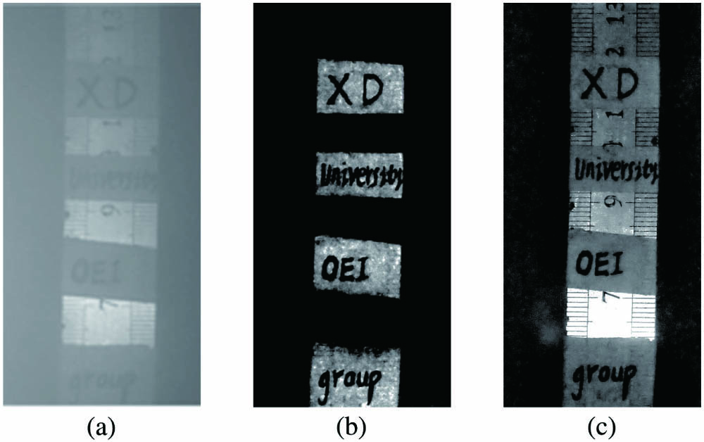
Figure 6 shows the experimental results obtained from using direct imaging and our polarization reconstruction method in the underwater environment. In Figs. 6(a)–6(d), the intensity images obtained directly by the detector experienced severe degradation. Furthermore, the presence of the backscattered light seriously reduced the image contrast and detection distance, whereas the influence of the backscattered light on imaging was significantly suppressed in the reconstruction results. In addition, the imaging field of view in Figs. 6(a) and 6(b) contained targets with different polarization characteristics. The experimental results showed that both the information sets of the two materials could be recovered simultaneously using the proposed method.
![]()
Figure 6.Experimental results. (a), (b), (c), and (d) are the intensity images obtained directly by the detector, and (e), (f), (g), and (h) are the reconstruction results obtained using the proposed method.
As an attempt to visualize the improvement resulting from using the proposed method, the curves in Figs. 7(a) and 7(b) were plotted, which represent the intensity profiles along the white, dotted lines crossing the middle of Figs. 6(a), 6(b), 6(e), and 6(f). In Fig. 6(a), due to the strong reflected light in the coin area and the influence of the backscattered light, the number on the coin cannot be recognized, and the curve in this area is extremely smooth with less detailed information of the target. Noticeably, the information provided in the coin area is observed in the detected image using the proposed method, and the numbers in the coin can thus be easily identified.
![]()
Figure 7.Visualizing the improvement resulting from using the proposed method. (a) and (b) are intensity profiles along the white dotted lines in Figs.
To analyze the degree of distortion in the reconstruction results obtained using different methods, the following simulation is conducted. A clear image without backscattered light is first acquired. Then, the total intensity image and polarization subimages are obtained by setting the intensity value of the backscattered light as well as the DOP and AOP of both the backscattered light (both were constants) and target-reflected light (both changed with the position of the pixels in the image)[
![]()
Figure 8.Simulated images. (a) Clear image. (b) Total intensity image. (c), (d), (e), and (f) are the 0°, 45°, 90°, and 135° polarization subimages, respectively.
Figure 9 shows the reconstruction results obtained by different methods. In order to facilitate the observation of distortions generated by different methods, we enhanced the details of the images in the second row. The traditional methods, such as image enhancement and Schechner’s method[
![]()
Figure 9.Simulation results. The images in the first row represent the reconstruction results obtained using different methods, the images in the second row represent the differences between the reconstruction results obtained using different methods and the original clear image, and the data below the images in the second row represent the degree of distortion of different methods.
4. Conclusion
In conclusion, this study utilized ICA to remove the backscattered light and accurately estimate the target information. Both the experimental and simulation results showed the effectiveness of our method. Compared with the other underwater polarization imaging methods, the proposed method could estimate the target information more accurately. In particular, for targets with different material properties, our method could accurately estimate their information simultaneously. Comparison of the degree of distortion estimated for the different underwater imaging methods showed that the proposed method produced the smallest distortion and could control the degree of distortion within 9%. This method is of great value in the field of underwater archaeology and shipwreck salvage where targets with nonuniform polarization characteristics need to be detected simultaneously.
References
[1] T. Treibitz, Y. Y. Schechner. Active polarization descattering. IEEE Trans. Pattern Anal. Mach. Intell., 31, 385(2009).
[2] F. Bruno, G. Bianco, M. Muzzupappa, S. Barone, A. V. Razional. Experimentation of structured light and stereo vision for underwater 3D reconstruction. ISPRS J. Photogramm. Remote Sensing, 66, 508(2011).
[3] C. S. Tan, G. Seet, A. Sluzek, D. M. He. A novel application of range-gated underwater laser imaging system (ULIS) in near-target turbid medium. Opt. Lasers Eng., 43, 995(2005).
[4] F. Liu, P. Han, Y. Wei, K. Yang, S. Huang, X. Li, G. Zhang, L. Bai, X. Shao. Deeply seeing through highly turbid water by active polarization imaging. Opt. Lett., 43, 4903(2018).
[5] C. Li, J. Wang, Q. Han, D. Bi. Lightness constancy: from haze illusion to haze removal. Chin. Opt. Lett., 10, 081001(2012).
[6] G. Jinge, M. Miao, S. Peng. Optimization of rotating orthogonal polarization imaging in turbid media via the Mueller matrix. Opt. Lasers Eng., 121, 104(2019).
[7] J. Izatt, M. R. Hee, G. M. Owen, E. A. Swanson. Optical coherence microscopy in scattering media. Opt. Lett., 19, 590(1994).
[8] H. Hu, L. Zhao, X. Li, H. Wang, T. G. Liu. Underwater image recovery under the nonuniform optical field based on polarimetric imaging. IEEE Photon. J., 10, 6900309(2018).
[9] K. He, J. Sun, X. Tang. Single image haze removal using dark channel prior. IEEE Trans. Pattern Anal. Mach. Intell., 33, 2341(2010).
[10] F. Liu, Y. Wei, P. Han, K. Yang, L. Bai, X. Shao. Polarization-based exploration for clear underwater vision in natural illumination. Opt. Express, 27, 13991(2019).
[11] B. Huang, T. Liu, H. Hu, J. Han, M. Yu. Underwater image recovery considering polarization effects of objects. Opt. Express, 24, 9826(2018).
[12] Y. Y. Schechner, S. G. Narasimhan, S. K. Nayar. Polarization-based vision through haze. Appl. Opt., 42, 511(2003).
[13] S. G. Demos, R. R. Alfano. Temporal gating in highly scattering media by the degree of optical polarization. Opt. Lett., 21, 161(1996).
[14] G. C. Giakos. Active backscattered optical polarimetric imaging of scattered targets. Proc. IEEE Instrum. Meas. Technol. Conf., 1, 430(2004).
[15] H. Tian, J. Zhu, S. Tan, Y. Zhang, Y. Zhang, Y. Li, X. Hou. Rapid underwater target enhancement method based on polarimetric imaging. Opt. Laser Technol., 108, 515(2018).
[16] H. Zhao, J. Xing, X. Gu, G. Jia. Polarization imaging in atmospheric environment based on polarized reflectance retrieval. Chin. Opt. Lett., 17, 012601(2019).
[17] K. Yan, S. Wang, S. Jiang, L. Xue, Y. Song, Z. Yan, Z. Li. Calculation and analysis of Mueller matrix in light scattering detection. Chin. Opt. Lett., 12, 092901(2014).
[18] M. Dubreuil, P. Delrot, I. Leonard, A. Alfalou. Exploring underwater target detection by imaging polarimetry and correlation techniques. Appl. Opt., 52, 997(2013).
[19] Y. Y. Schechner, N. Karpel. Clear Underwater Vision(2004).
[20] X. Fu, Z. Liang, X. Ding, X. Yu, Y. Wang. Image descattering and absorption compensation in underwater polarimetric imaging. Opt. Lasers Eng., 132, 106115(2020).
[21] X. Li, F. Liu, X. Shao. Research progress on polarization 3D imaging technology. J. Infrared Millim. Waves, 40, 248(2021).
[22] J. E. Solomon. Polarization imaging. Appl. Opt., 20, 1537(1981).
[23] X. Li, F. Liu, P. Han, S. Zhang, X. Shao. Near-infrared monocular 3D computational polarization imaging of surfaces exhibiting nonuniform reflectance. Opt. Express, 29, 15616(2021).
[24] B. Peng, S. Huang, D. Li. Detection of colorless plastic contaminants hidden in cotton layer using chromatic polarization imaging. Chin. Opt. Lett., 13, 092901(2015).
[25] J. Liang, W. Zhang, L. Ren, H. Ju, E. Qu. Polarimetric dehazing method for visibility improvement based on visible and infrared image fusion. Appl. Opt., 55, 8221(2016).
[26] P. Han, F. Liu, Y. Wei, X. Shao. Optical correlation assists to enhance underwater polarization imaging performance. Opt. Lasers Eng., 134, 106256(2020).
[27] S. Umeyama, G. Godin. Separation of diffuse and specular components of surface reflection by use of polarization and statistical analysis of images. IEEE Trans. Pattern Anal. Mach. Intell., 26, 639(2004).
[28] Y. Wei, P. Han, F. Liu, X. Shao. Enhancement of underwater vision by fully exploiting the polarization information from the Stokes vector. Opt. Express, 29, 22275(2021).
[29] L. Jian, R. Liyong, J. Haijuan, Q. Enshi. Visibility enhancement of hazy images based on a universal polarimetric imaging method. J. Appl. Phys., 116, 173107(2014).


Set citation alerts for the article
Please enter your email address

© Copyright 2018-2021 | Chinese Laser Press. All Rights Reserved 沪ICP备15018463号-20