1Key Laboratory of Material Physics, Ministry of Education, School of Physics and Microelectronics, Zhengzhou University, Zhengzhou 450052, China
2Key Laboratory of Opto-Electronics Information Technology (Tianjin University), Ministry of Education, School of Precision Instruments and Opto-Electronics Engineering, Tianjin University, Tianjin 300072, China
3Beijing Key Laboratory for Metamaterials and Devices, Key Laboratory of Terahertz Optoelectronics, Ministry of Education, and Beijing Advanced Innovation Center for Imaging Technology, Department of Physics, Capital Normal University, Beijing 100048, China
4State Key Laboratory of Modern Optical Instrumentation, College of Optical Science and Engineering, Zhejiang University, Hangzhou 310027, China
【AIGC One Sentence Reading】:A novel metasurface-based polarimeter allows for complete polarization detection with just one measurement, enabling fast and accurate terahertz polarization analysis crucial for real-time applications and integrated optics.
【AIGC Short Abstract】:Polarization detection is essential in various applications. This study presents a multifocus metalens for terahertz polarization detection, enabling complete polarization parameters and state reconstruction with just one measurement. The metalens' subarrays convert polarized components to the same polarization, linking Stokes parameters to six foci. Both simulations and experiments confirm accurate polarization detection with this method, offering potential for real-time terahertz detection and integrated optics.
Note: This section is automatically generated by AI . The website and platform operators shall not be liable for any commercial or legal consequences arising from your use of AI generated content on this website. Please be aware of this.
Abstract
Polarization is crucial in various fields such as imaging, sensing, and substance detection. A compact, fast, and accurate polarization detection device is vital for these applications. Herein, we demonstrate a multifocus metalens for terahertz polarization detection that requires only a single measurement to obtain complete polarization parameters and reconstruct the polarization state of the incident field. The individual subarrays of this metalens convert each of the six polarized components into the same polarization, which in turn links the Stokes parameters to these six foci. The incident linear polarizations and elliptical polarizations are characterized by Stokes parameters and polarization ellipses. Simulations and experimental results show that the scheme can accurately detect the incident polarization with a single measurement. The proposed metasurface polarimetry may find applications in the fields of real-time terahertz detection and integrated optics.
1. INTRODUCTION
Metasurfaces, by introducing phase discontinuities at the interface, are capable of modulating incident waves on a subwavelength scale [1]. This breaks the limitations of traditional optics and provides greater freedom in controlling electromagnetic waves. Based on the generalized Snell’s law, researchers have proposed versatile metasurfaces [2,3], realizing various physical phenomena and devices such as metaholography [4–6], metalenses [7–10], vortex beams [11–13], vector polarization [14,15], and surface waves [16]. Lenses are widely used in optics, biology, medicine, security, and other fields. The emergence of metalenses has made these devices more compact and introduced new functionalities. Researchers have designed various metalenses, including polarization-insensitive, polarization-tunable, and achromatic metalenses [17–22]. Chen et al. demonstrated a planar lens based on helicity-dependent phase discontinuities [17]. By controlling the incident polarization, controllable real and virtual focal planes were observed using the same metalens. Capasso et al. used high-aspect-ratio nanopillars to construct a millimeter-scale metalens, achieving imaging performance comparable to advanced commercial objectives [18]. Wang et al. proposed a method for achromatic metasurfaces, successfully eliminating chromatic aberration in the wavelength range of 1200 to 1680 nm [19]. Duan et al. presented a polarization-switchable multifocus metalens, demonstrating applications such as polarization detection and zoom imaging [20].
Polarization, as important information carried by electromagnetic waves, is crucial in imaging, encryption, image processing, and other fields. How to generate specific polarization states, how to identify the polarization state of electromagnetic waves, and how to utilize polarization are all research hotspots. For the recognition of polarization states, traditional approaches include measurement through rotating polarizers or phase retarders, as well as the divisions of amplitude and aperture [23–25]. These traditional methods are bulky and not conducive to integration. Researchers have combined the manipulation characteristics of metasurfaces to propose some polarization detection devices [26–32]. Wen et al. utilized the principle of geometric phase to deflect the left-handed and right-handed components of the incident wave in opposite directions, thereby measuring the ellipticity and handedness of polarized light [28]. Zhang et al. proposed a dielectric metasurface for wide-angle polarization detection [29]. Hu et al. used polarization filters to propose Stokes metasurfaces in the near-infrared waveband [30]. Wang et al. proposed a single-layer metasurface spectrometer based on the intrinsic dispersion and multifocus property of the metalens [31]. Especially for the terahertz band, there is an urgent need to develop efficient and compact polarization detection devices. Wang et al. proposed a reflective four-focus metalens for terahertz polarization detection. The polarization information of terahertz waves is obtained based on the intensity of the focal points [33]. Nowack et al. proposed a metasurface polarization detector for the terahertz band, utilizing three sublattices [34]. Jiang et al. proposed a metasurface-like metallic waveguide array to detect continuous terahertz waves [35]. However, these polarization detection schemes require multiple measurements to obtain the required polarization information. For those metasurfaces using multifocus metalenses for polarization detection, they can obtain the intensities of all foci by a single measurement in the visible or infrared band. However, it should be noted that these foci are of different polarization states, including linear polarizations and circular polarizations. If the above schemes are transplanted to the terahertz band, where only a single polarization field can be measured at a time, the intensities of these foci with different polarization states cannot be obtained by a single measurement.
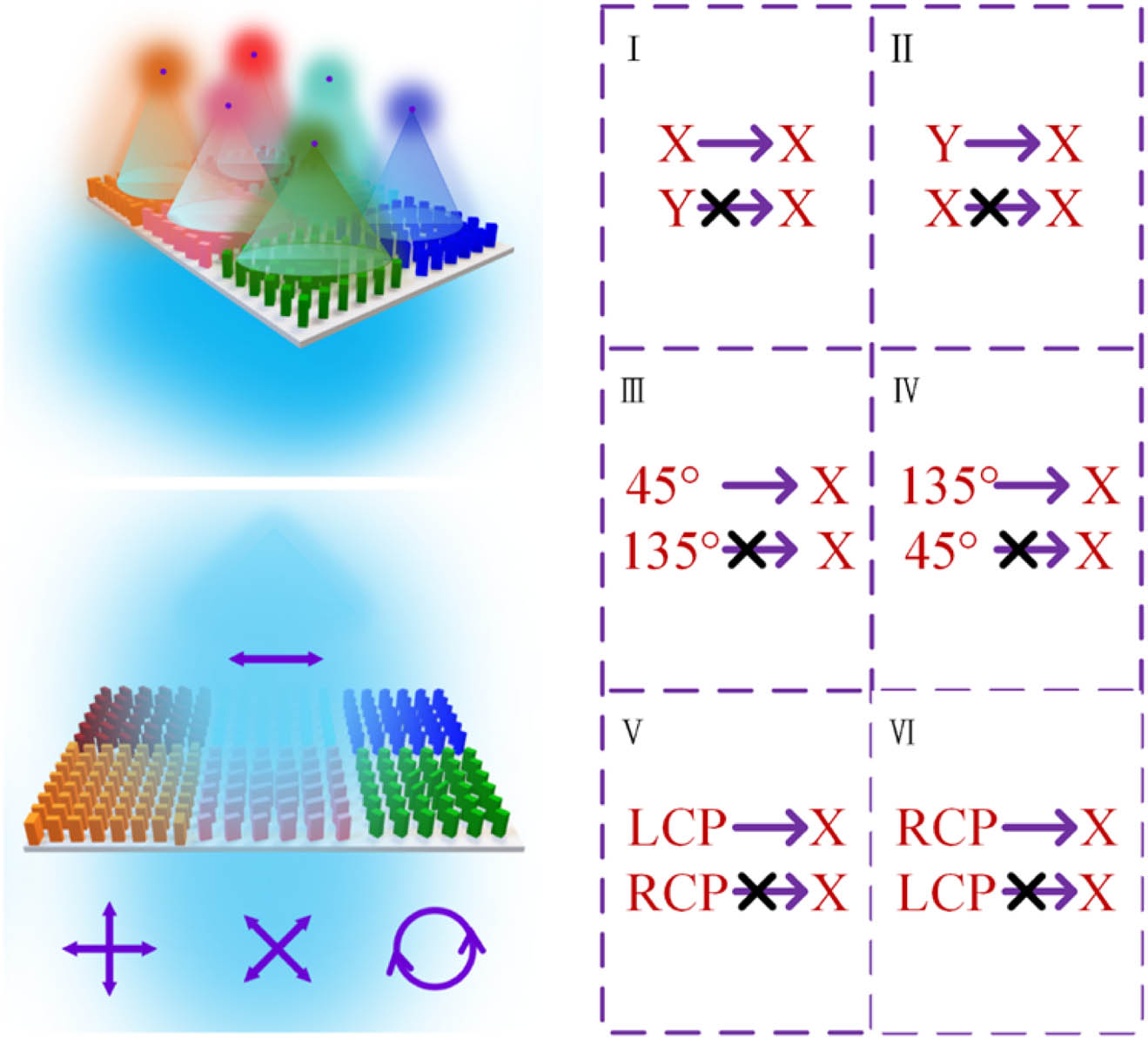
In this work, we propose a multifocus metalens for polarization detection in the terahertz band. Unlike previously reported two-focus or six-focus metalenses used for polarization detection [28,29,36], or some other polarization detection schemes, the proposed metasurface converts all polarization components used to characterize Stokes parameters into the same polarization state, ensuring that only a single measurement is needed to obtain complete polarization parameters and reconstruct the polarization state of the incident field. This provides a new option for real-time polarization detection in the terahertz band and can be extended to visible light and other electromagnetic bands. The proposed metasurface consists of six subarrays (Fig. 1); each subarray sequentially focuses -polarized, -polarized, 45°-polarized, 135°-polarized, left-handed circularly polarized (LCP), and right-handed circularly polarized (RCP) components in the incident wave and converts them into polarization. These subarrays only focus their corresponding polarization components onto the focal plane, excluding their orthogonal polarization states. This ensures that the intensity at each focus corresponds to the intensity of a certain polarization component in the incident field. The polarization state of the incident wave can be reconstructed using the intensities of the six foci. We employ this metalens to detect linear polarizations, circular polarizations, and elliptical polarizations. Simulations and experimental results demonstrate the feasibility of this metalens for polarization detection. This metalens holds great potential for applications in efficient and compact polarization devices and polarization optics.
Sign up for Photonics Research TOC. Get the latest issue of Photonics Research delivered right to you!Sign up now
Figure 1.Schematic of the proposed multifocus metalens for polarization detection. For arbitrarily polarized wave incidence, this metalens converts each of the six polarized components (-polarized, -polarized, 45°-polarized, 135°-polarized, LCP, and RCP) of the incident wave into polarization and focuses them individually at six positions on the same focal plane.
The proposed metasurface for polarization detection consists of six subarrays, each of which converts its responsible polarization state into polarization and focuses on the focal plane. Here, we divide the metasurface into six parts to introduce how to design the meta-atoms of each subarray so as to complete the design of the entire metasurface. At its most basic, the entire metasurface is made of high-resistance silicon with a dielectric constant of 11.9. The heights of all silicon pillars are 200 μm, and their operating frequencies are selected as 0.9 THz.
For the first part, the goal is to focus the -polarized component of the incident field on the focal plane, discarding the -polarized component. We select 64 meta-atoms through parametric scanning to ensure that the phase shifts of the transmitted and components are independent under the - or -polarized incidence. The detailed structural parameters (length and width) of these meta-atoms are listed in Tables 1 and 2 (Appendix A). We select eight of these meta-atoms and plot their phase shifts in Fig. 2(a). Their phase shifts cover the range with a gradient under the -polarized incidence. In the case of -polarized incidence, their phases are almost constant. Using these selected 64 meta-atoms, the phase profiles of - and -polarized incidences are expressed as where the focal length is set as . With the phase profiles in Eq. (1), the -polarized component of the incident field can be focused on the focal plane, while the -polarized component cannot. It is worth noting that the next five parts all adopt the phase profile in Eq. (1).
Detailed Structural Parameters (Length ) of the Selected 64 Meta-atoms
1
2
3
4
5
6
7
8
1
66
70
74
88
54
58
62
64
2
58
140
66
76
48
50
56
58
3
50
122
122
64
138
44
48
48
4
30
36
98
112
122
128
30
30
5
128
140
80
80
94
102
114
116
6
98
110
120
68
74
80
86
90
7
78
82
98
138
64
70
74
76
8
72
76
82
120
58
62
68
68
Detailed Structural Parameters (Width ) of the Selected 64 Meta-atoms
1
2
3
4
5
6
7
8
1
66
58
50
36
128
96
78
72
2
70
140
52
38
138
112
82
74
3
74
140
126
40
80
120
90
82
4
104
78
132
108
82
70
140
120
5
54
48
136
126
90
74
64
60
6
58
50
44
132
102
82
70
64
7
62
56
44
32
116
86
72
68
8
64
56
48
30
126
96
74
70
Figure 2.Characterization of the selected meta-atoms. (a) Simulated phase shifts of the transmitted -polarized (-polarized) component under the -polarized (-polarized) incidence; (b) simulated transmission amplitudes and phase shifts of the transmitted -polarized component under the -polarized incidence; (c) transmission amplitudes and phase shifts of the transmitted -polarized component under the 45°-polarized incidence; (d) transmission amplitudes and phase shifts of the transmitted -polarized component under the 135°-polarized incidence; (e) transmission amplitudes and phase shifts of the transmitted -polarized component under the LCP incidence; (f) transmission amplitudes and phase shifts of the transmitted -polarized component under the RCP incidence.
For the second part, we want to convert the incident -polarized wave into polarization and focus it. To achieve such a polarization conversion, the Jones matrix of meta-atoms can be written as
For any polarization state incident , the transmitted field can be expressed as Eq. (B1). If we only detect the -polarized component of the transmitted field, we can find that the intensity of the transmitted -polarized component is only related to the -polarized component of the incident wave. In order to maintain a high polarization-conversion efficiency, we place the rectangular pillars in a 45° orientation [as shown in the inset of Fig. 2(b)] and vary their lengths and widths for parametric scanning. The simulated transmission amplitudes and phase shifts of the selected eight meta-atoms are shown in Fig. 2(b). They are the transmitted -polarized component under the -polarized incidence. Their amplitudes are around 0.7 and cover a phase range of . Using these meta-atoms to design a metalens, the intensity of the focus can be used to characterize the proportion of the -polarized component in the incident wave.
The Jones matrix of the meta-atoms in the third part can be written as Eq. (3). These meta-atoms can convert the 45°-polarized component of the incident wave into polarization and will not perform such a conversion for its orthogonally polarized component (135° polarization),
For an arbitrarily polarized wave incident on this part, the modulation of the meta-atoms on the incident wave can be described by Eq. (B2). It can be seen that the intensity of the -polarized component of the transmitted field is related to the 45° polarization in the incident wave, which can be used to characterize the intensity of the 45°-polarized component.
Here, we fix the orientation of the meta-atoms to 22.5° and perform parametric sweeps. The amplitudes and phase shifts of the selected eight meta-atoms are shown in Fig. 2(c). They are the transmitted -polarized component under the 45°-polarized incidence.
We rotate the meta-atoms of the third part by 45° to obtain the meta-atoms of the fourth part. Their Jones matrix can be written as Eq. (4), which converts the incident 135° polarization into polarization [as described in Eq. (B3)]. In this case, the intensity of the transmitted -polarized component is related to the 135° polarization in the incident field,
For the fifth part, the meta-atoms convert the incident LCP wave into an -polarized component. This requires that these meta-atoms are all quarter-wave plates, which means that they have the same amplitudes under the - and -polarized incidences, but a phase difference of . For a quarter-wave plate with a rotation angle of 45°, its Jones matrix can be written as
For the LCP and RCP components in the incident wave, the modulations of Jones matrix can be described by Eq. (B4). The intensity of the -polarized component of the transmitted field is related to the LCP component in the incident wave.
We select eight quarter-wave plates by parametric scanning, and their amplitudes and phase shifts of the transmitted polarization under the LCP incidence are shown in Fig. 2(e). For the sixth part, we just need to rotate the meta-atoms in the fifth part by 90°. Their Jones matrix is expressed as Eq. (6). This allows only the RCP component of the incident wave to be converted into the transmitted polarization,
Using these six groups of meta-atoms, a metalens is constructed in each part, and the polarization parameters of the incident field can be quickly obtained using the intensity of the -polarized component at the focal plane, and then reconstructing its polarization state. The relationships between the Stokes parameters of the incident polarization state and the intensities of each focus are defined as follows:
3. RESULTS AND DISCUSSION
Considering the differences in the polarization conversion efficiencies of the meta-atoms in the six subarrays, first polarization, polarization, 45° polarization, 135° polarization, LCP, and RCP components are incident to this metalens to obtain the maximum value of each focus. Their intensity distributions are shown in Fig. 7 (Appendix C). In the subsequent applications, the values of each focus will be normalized with these six values, and then the Stokes parameters will be calculated.
To validate the capability of the proposed metalens in polarization detection, we first set the incident polarization to a series of linear polarization states with different azimuth angles (, , , , , , , and ). We simulate the transmitted field of the metalens under each linearly polarized incidence in turn. Please note that we only need the information of the -polarized component of the transmitted field, not the other polarized components or the total field. The same condition applies to all the analyses that follow. The intensity distributions of the transmitted -polarized component are shown in the first row in Figs. 3(c)–3(j). The intensity of the fourth focus gradually decreases, and the intensity of the third continues to increase as the azimuth angle increases from to . Correspondingly, the Stokes parameter gradually increases from to 1 (Fig. 8 in Appendix C). Using the solved Stokes parameters (, , ), we can also calculate the amplitude ratios and phase differences of the and polarizations in the incident waves and plot the polarization ellipses of each polarization state. The comparisons of the detected polarization states and the incident ones are shown in the second row of Figs. 3(c)–3(j). The detected polarization states maintain the same azimuthal angles as the incident polarizations. We plot the comparison of the azimuth angles of the detected polarizations and the incident ones in Fig. 3(b), and their consistency can be seen quantitatively. We also present them as points on the Poincaré sphere in Fig. 3(a), which follow the equatorial direction from the negative to the positive direction of the axis. The consistencies of the detected polarizations with the incident ones are compared through a variety of polarization representations, demonstrating the accuracy of the proposed metalens for the detection of linear polarization states.
Figure 3.Characteristic of the proposed multifocus metalens for polarization detection: eight linearly polarized incidences. (a) Representation as points on the Poincaré sphere of the detected polarizations () and the incident ones (hexagrams); (b) comparison of the simulated azimuth angles and the theoretical ones; (c)–(j) intensity distribution of the transmitted -polarized component and the comparison of polarization ellipses between the detected polarization states (red) and the incident ones (blue).
In this part, we select eight elliptically polarized incidences to examine the performance of the proposed polarization detector, all of which have an azimuthal angle of zero. Their axial ratios are 0.8, 0.6, 0.4, and 0.2. The first four polarization states have right-handed spins and the last four are left-handed. The simulated intensity distributions of the transmitted -polarized component are shown in the first row of Figs. 4(c)–4(j). For the first four results [Figs. 4(c)–4(f)], their incident waves are all right-handed elliptically polarized. As the axial ratio decreases from 0.8 to 0.2, the intensity difference between the first focus and the second one becomes larger, resulting in a gradual increase in the value of [Fig. 4(b)]. At the same time, the intensity differences between the sixth and fifth foci gradually decrease, resulting in a decreasing trend in . Figures 4(g)–4(j) show the corresponding intensity distributions and the comparisons of polarization ellipses when the incident waves are left-handed elliptically polarized. Their axial ratios are 0.2, 0.4, 0.6, and 0.8, respectively. The intensity of the first focus gradually weakens with respect to the second focus, and the corresponding Stokes parameter gradually decreases. The fifth focus gradually strengthens, leading to a continued decrease in the parameter . Throughout the process, the intensities of the third and fourth foci remain consistent, with parameter almost equal to zero. This aligns with the incident polarizations having an azimuth angle of zero. According to the parameters of the detected polarization states, we also represent them as points on the Poincaré sphere in Fig. 4(a). Their trajectory follows the meridian from the positive direction to the negative direction of the axis. The detected polarization states remain essentially the same as the incident ones.
Figure 4.Characteristic of the proposed multifocus metalens for polarization detection: eight elliptically polarized incidences (along the meridian direction). (a) Representation as points on the Poincaré sphere of the detected polarizations () and the incident ones (hexagrams); (b) full-Stokes parameters of the detected polarization states (purple) and the incident ones (orange); (c)–(j) intensity distributions of the transmitted -polarized component and the comparisons of polarization ellipses between the detected polarization states (red) and the incident ones (blue).
In addition to the detection of some linear polarizations and elliptical polarizations with an azimuthal angle of zero in the previous two parts, we also detect some elliptical polarizations with arbitrary azimuthal angles and ellipticities. The first five states are left-handed elliptical polarizations, and their axial ratios and azimuth angles are (0.4, ), (0.6, ), (0.8, ), (0.8, ), and (0.2, ), respectively. For the last three right-handed elliptical polarizations, their parameters are (0.5, ), (0.3, ), and (0.7, ), respectively. Their intensity distributions of the transmitted -polarized component are shown in Fig. 9 (Appendix C). Under the first five elliptically polarized incidences, the intensities of the fifth focus are larger than that of the sixth, demonstrating a larger proportion of left-handedness in the incident polarizations. For the last three, the right-handedness is more predominant than the left-handedness. Based on the intensity differences among these three pairs of foci, three Stokes parameters are calculated, as shown in Fig. 5(a). These elliptical polarizations all have a larger percentage of -polarized components than polarizations, and their parameters are essentially positive. For the parameter , they are greater than zero when the values of the azimuth angles are positive. The comparisons of polarization ellipses between the detected polarization states and the incident ones are shown in Figs. 5(c)–5(j). The red ellipses basically show the same curves as the blue ones. Their points on the Poincaré sphere almost coincide, again demonstrating the accuracy of the detected polarization states.
Figure 5.Characteristic of the proposed multifocus metalens for polarization detection: eight arbitrarily elliptically polarized incidences. (a) Full-Stokes parameters of the detected polarization states (purple) and the incident ones (orange); (b) representation as points on the Poincaré sphere of the detected polarizations () and the incident ones (hexagrams); (c)–(j) comparisons of polarization ellipses between the detected polarization states (red) and the incident ones (blue).
We fabricate a sample of the multifocus metalens proposed in this work using standard ultraviolet lithography and inductively coupled plasma etching processes. The height of the fabricated sample is 500 μm, the etching depth is 200 μm, and the size of the sample is . We select two areas and take their scanning electron micrograph (SEM) images, as shown in Figs. 6(a) and 6(b). The focusing behavior and the capabilities of polarization detection are examined by using a laboratory-built terahertz digital holographic imaging system [37]. Figures 6(d)–6(i) illustrate the measured intensity distributions of the transmitted field when the incident waves are -polarized, -polarized, 45°-polarized, 135°-polarized, LCP, and RCP, respectively. For - and -polarized wave incidences, the incident polarization states can be inferred from the large contrast between the first and second foci. The calculated parameters are close to 1 and , respectively. For the 45° and 135° polarizations, the intensities of the third and fourth foci are significantly different, with the parameter close to 1 and , respectively. When the incident waves are circularly polarized, the intensity differences are mainly reflected in the fifth and sixth foci, and their corresponding parameters are close to the theoretical and 1, respectively. We similarly compare the experimentally detected polarization states with the incident ones on the same Poincaré sphere, and these six polarization states are in each of the six directions of the three coordinate axes. The experimentally measured points are very close to the theoretical values.
Figure 6.Experimental characterization of the proposed multifocus metalens for polarization detection. (a), (b) SEM images of the fabricated metasurface; (c) representation as points on the Poincaré sphere of the measured polarizations () and the incident ones (hexagrams); (d)–(i) measured intensity distributions of the transmitted -polarized component, and full-Stokes parameters of the measured polarization states and the incident ones.
To quantitatively characterize the accuracy of the proposed metasurface polarization detection scheme, we list the Stokes parameters for six typical polarization states in Table 3 (Appendix C) and calculate the detection error for each polarization state. Here, the average error is defined as
The maximum detection error of the simulation results is 0.021, and the average error is 0.0136, which is in good agreement with the theoretical results. In the experiment, these two values are 0.0839 and 0.0592, respectively. These errors may originate from: (1) the amplitude and phase responses of the selected meta-atoms (which are not as perfect as theoretically); (2) the signal-to-noise ratio of the test system.
4. CONCLUSION
In conclusion, we demonstrate a polarization detection scheme that requires only a single measurement. The implementation of the scheme is based on a six-focus metalens, which converts six polarization states used to characterize Stokes parameters into polarization and focuses them. Thus, the complete polarization parameters can be obtained by measuring only the transmitted -polarized response. The full-Stokes parameters of the incident fields can be calculated from the intensities of the six foci, and they are also characterized by polarization ellipse and Poincaré sphere. The detection results of various linear polarizations and elliptic polarizations demonstrate the capability of this scheme in polarization detection. The practicality of this approach is also tested experimentally by fabricating a sample. This efficient polarization detection scheme may find applications in fields such as integrated optics and polarized optics.
APPENDIX A: THE DETAILED STRUCTURAL PARAMETERS OF THE SELECTED 64 META-ATOMS FOR THE FIRST SUBARRAY
The detailed structural parameters of the selected 64 meta-atoms are listed in Tables 1 and 2, where the numbers 1 to 8 represent phases 0 to . The columns correspond to the phase of the transmitted -polarized wave and the rows correspond to the phase of the transmitted -polarized wave.
APPENDIX B: TRANSMITTED FIELD DISTRIBUTIONS AFTER THE MODULATIONS OF DIFFERENT META-ATOMS
For the second part, we want to convert the incident -polarized wave into polarization and focus it. For any polarization state incident , the transmitted field can be expressed as
For an arbitrarily polarized wave incident on the third part, the modulation of the meta-atoms on the incident wave can be described as
For the meta-atoms in the fourth part, they can be obtained by rotating the meta-atoms of the third part by 45°. Their modulation of the incident wave can be described as
For the fifth part, the modulations of the incident LCP and RCP components by the Jones matrix can be described as
APPENDIX C: INTENSITY DISTRIBUTIONS AND STOKES PARAMETERS
The intensity distributions of the transmitted x-polarized component under the incidences of x polarization, y polarization, 45° polarization, 135° polarization, LCP, and RCP light are shown in Fig. 7. The full-Stokes parameters of the detected polarization states and the incident ones under different linearly polarized incidences are shown in Fig. 8. In Fig. 9, the intensity distributions of the transmitted x-polarized component under arbitrarily elliptically polarized incidences are exhibited. We also carry out comparison and error analysis of the theoretical, simulated, and measured Stokes parameters, as shown in Table 3.
Figure 7.Intensity distributions of the transmitted -polarized component under the different polarized incidences.
 AI Video Guide
  AI Picture Guide
 AI One Sentence