
Dawei Cao, Ming Li, Jianfei Zhu, Yanfang He, Tong Chen, Yuan Liu, Mingming Chen, Ying Yang. Enhancement of photoelectrochemical performance in ferroelectric films via the introduction of an Au buffer layer[J]. Journal of Semiconductors, 2021, 42(11): 112701
- Journal of Semiconductors
- Vol. 42, Issue 11, 112701 (2021)
Abstract
1. Introduction
The excessive development of non-renewable resources and the aggravation of ecological pollution make the rational development and utilization of solar energy seem particularly important[
Recently, as a typical ferroelectric material, BiFeO3 (BFO) has attracted a lot of interest owing to its robust ferroelectricity, relatively small band gap (~2.3 eV), and strong absorption of visible light[
Herein, we deposited Au buffer layer on FTO glass as a substrate to prepare an efficient FTO/Au/BFO photoelectrode. The effect of Au buffer layer on BFO performance was systematically studied, and the Au/BFO photoelectrode exhibited an extraordinary improvement in PEC water splitting due to the improvement of charge separation efficiency under light irradiation. More importantly, the ferroelectric polarization electric field (Ep) enables the electron–hole pairs in the photoelectrode to be more effectively separated and they also reduce carrier recombination. The PEC performance of Au/BFO photoelectrode was further improved by applying a polarized electric field. Therefore, this research provides a new idea to explore and enhance the PEC performance of ferroelectric films.
2. Experiments
2.1. Materials and chemicals
The chemical reagents used in this experiment were all purchased from Sinopharm Chemical Reagents Co., Ltd., with analytical purity, which can be used directly.
2.2. Preparation of FTO/Au/BFO photoelectrode
In this work, FTO/Au/BFO photoelectric electrodes were prepared by magnetron sputtering and sol-gel method. BFO precursor solution was prepared according to the method reported previously[
2.3. PEC measurements
The PEC characteristics of the sample were tested using a three-electrode system electrochemical workstation. Among them, the pair electrode was Pt sheet, Ag/AgCl as the reference electrode, and the sample was used as working electrode (further details can be found in the Supporting Information).
2.4. Characterizations
The X-ray diffraction (XRD) spectrum was used to study the crystal structure of the samples (Bruker D8). A field emission scanning electron microscopy (JEOL, 7800F) was used to study the surface morphology of photoelectrode. UV–Vis spectrophotometer (SHIMADZU, UV2600) was used to characterize the light absorption of the films.
3. Results and discussion
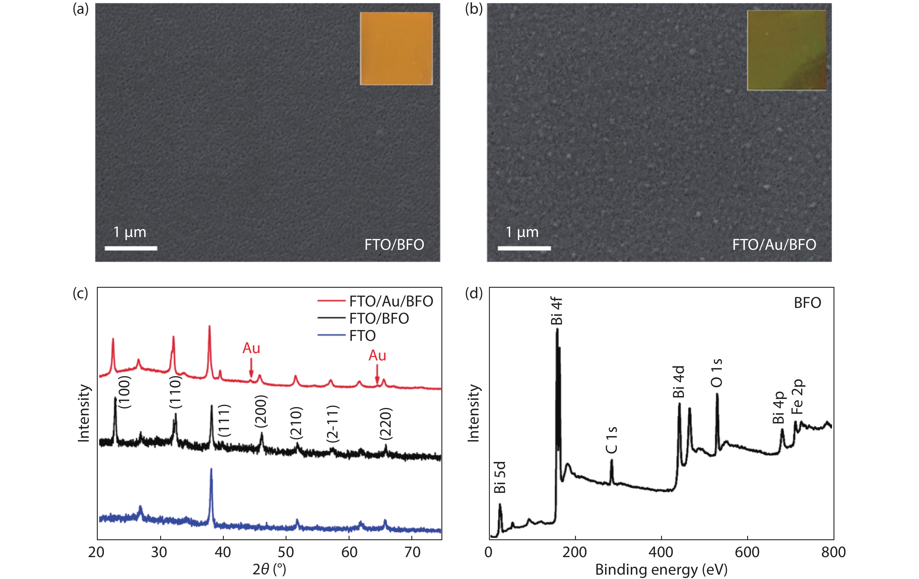
In this experiment, BFO films were prepared on FTO and FTO/Au substrates by a simple sol-gel method. We observed the morphology of the samples with a scanning electron microscope (SEM), as shown in Fig. 1. In Fig. 1(a), the obtained BFO films show an irregular porous structure on a uniform surface. Obviously, FTO/Au/BFO images still show porous structures, but the density of surface defects on the surface of the sample was significantly reduced (Fig. 1(b)). Through SEM image analysis, we believe that the existence of the Au film was the key factor to improve the crystallization of BFO film. In addition, there is a clear interface between BFO and FTO in the cross-section image of the Au/BFO sample (see Supporting Information, Fig. S1), but the Au buffer layer was too thin to be observed in the image.
![]()
Figure 1.(Color online) SEM images of (a) BFO and (b) Au/BFO. (c) XRD spectra of BFO and Au/BFO. (d) XPS spectra of BFO.
The crystal structures of Au/BFO and BFO were revealed by XRD patterns in Fig. 1(c). The BFO films presents a polycrystalline structure, and the location of characteristic peaks on each crystal plane is consistent with the data of PDF standard card reported previously (No. 72-2112). No diffraction peaks of other impurities were found, which indicates that the preparation of BFO films was successful. Compared to FTO/BFO, the characteristic peak of Au appears in the diffraction peak of FTO/Au/BFO, which undoubtedly confirms the existence of Au[
Fig. 2(a) shows density–voltage (J–V) curves of the FTO/BFO and FTO/Au/BFO photoelectrodes. Both BFO and Au/BFO showed photocathode characteristics in accordance with the literature reports[
![]()
Figure 2.(Color online) (a)
To explore the influence of the Au buffer layer on the light absorption performance of photoelectrode, we used an UV–vis spectrophotometer to study the light absorption of the two samples in the wavelength range of 300–800 nm. Compared with the BFO photoelectrode, the light absorption capacity of the whole region was slightly improved after the introduction of Au buffer layer (Fig. 3(a)). In addition, the effect of Au buffer layer on light absorption was further explained by calculating the light harvesting efficiency (ηLHE) of the photoelectrode. We calculate ηLHE with the absorbance data ηabs:
![]()
Figure 3.(Color online) (a) Absorbance spectra, (b) light harvesting efficiencies (
where ηabs = 100 – transmittance (T) – reflectance (R)[
Meanwhile, the electron flux on the photoelectrode in the wavelength range of 300–420 nm was integrated to calculate the photocurrent density (Jabs) at 100% absorption photon conversion efficiency, and the results are shown in Fig. 3(c). Jabs were estimated to be –1.917 and –1.918 mA/cm2 for BFO and Au/BFO, respectively, with only slight differences between them. This further indicates that in our experiment, the improvement of PEC performance of Au/BFO photoelectrode was not the main effect of light absorption. In general, the effective separation characteristics of photo-generated charge are conducive to improving the PEC performance of the photoelectrode. AgNO3 is usually added to the electrolyte as an electron scavenger for P-type semiconductors to investigate the charge separation efficiency in the PEC system[
Rapid separation of photogenerated carriers is crucial for enhanced PEC activity[
![]()
Figure 4.(Color online) (a) The PL spectra and (b) transient PL decay spectra of BFO and Au/BFO.
Electrochemical impedance spectroscopy (EIS) was used to further analyze the reasons for the improved PEC performance of the photoelectrode[
![]()
Figure 5.(Color online) (a) Nyquist plots of electrochemical impedance spectra and (b) Mott-Schottky plots of BFO and Au/BFO.
where e, Nd, ε, ε0 and V correspond to electron charge, carrier density, dielectric constant, permittivity of vacuum and applied bias at the electrode, respectively. As depicted in Fig. 5(b), the fitting line of the Mott-Schottky curve slope shows that the Mott-Schottky curve slope of Au/BFO electrode was relatively low, signifying the high carrier density. It is well-known that the increase of carrier density can promote the separation and transfer of photoexcited electrons, thus reducing the occurrence of photogenerated electrons and hole recombination, which is of great significance to improve the PEC performance of photoelectrodes.
Based on these results, the charge transfer mechanism in Au/BFO photoelectrodes will be discussed. The work function of FTO, Au and BFO are 4.9, 5.1 and 4.8 eV, respectively[
![]()
Figure 6.(Color online) (a) Schematic of work function of FTO, Au and BFO. Schematic of the electron-transfer mechanism of (b) FTO/BFO and (c) FTO/Au/BFO. The photogenerated carrier transfer mechanism of Au/BFO photoelectrode under (d) no poling, (e) positive poling and (f) negative poling.
4. Conclusion
In summary, an FTO/Au/BFO photoelectrode was prepared by introducing an Au buffer layer by magnetron sputtering. This can not only significantly improve the PEC performance of the photoelectrode but also improve its stability. The results demonstrate that the significant improvement of PEC performance of Au/BFO photoelectrode in this experiment was not mainly dependent on light absorption. The presence of the Au buffer layer can reduce the resistance of charge transfer, promote the transport of the charge carriers and improve the charge separation efficiency, which was an important reason to enhance the performance of PEC. In addition, ferroelectric polarization can further accelerate the separation and transport of photoelectric–hole pairs and improve the photoelectric conversion efficiency of PEC system. The introduction of the Au buffer layer enhances the charge separation of ferroelectric thin films, which provides an effective idea for the preparation of efficient photoelectrode.
Acknowledgements
This work was supported by National Natural Science Foundation of China (Grant No. 51702130), the Innovation/Entrepreneurship Program of Jiangsu Province and the project of Zhenjiang Key Laboratory of Advanced Sensing Materials and Devices (No. SS2018001). D. C. appreciates the support from Jiangsu Specially-Appointed Professors Program.
Appendix A. Supplementary materials
Supplementary materials to this article can be found online at https://doi.org/1674-4926/42/11/112701.
References
[1] H Zhao, Y Lei. 3D nanostructures for the next generation of high-performance nanodevices for electrochemical energy conversion and storage. Adv Energy Mater, 10, 2001460(2020).
[2] P Wang, G Li, M Wang et al. Numerical study of mono-crystalline silicon solar cells with passivated emitter and rear contact configuration for the efficiency beyond 24% based on mass production technology. J Semicond, 41, 062701(2020).
[3] S Wang, Y Wang, S L Zhang et al. Supporting ultrathin ZnIn2S4 nanosheets on Co/N-doped graphitic carbon nanocages for efficient photocatalytic H2 generation. Adv Mater, 31, 1903404(2019).
[4] N Nasori, T Dai, X Jia et al. Realizing super-long Cu2O nanowires arrays for high-efficient water splitting applications with a convenient approach. J Semicond, 40, 052701(2019).
[5] H Zhu, M Sha, H Zhao et al. Highly-rough surface carbon nanofibers film as an effective interlayer for lithium-sulfur batteries. J Semicond, 41, 092701(2020).
[6] S P Berglund, F F Abdi, P Bogdanoff et al. Comprehensive evaluation of CuBi2O4 as a photocathode material for photoelectrochemical water splitting. Chem Mater, 28, 4231(2016).
[7] S Feng, T Wang, B Liu et al. Enriched surface oxygen vacancies of photoanodes by photoetching with enhanced charge separation. Angew Chem Int Ed, 59, 2044(2020).
[8] M Ma, Y Huang, J Liu et al. Engineering the photoelectrochemical behaviors of ZnO for efficient solar water splitting. J Semicond, 41, 091702(2020).
[9] X Guo, Q Liu, H Tian et al. Optimization of broadband omnidirectional antireflection coatings for solar cells. J Semicond, 40, 032702(2019).
[10] Y Deng, J Liu, Y Huang et al. Engineering the photocatalytic behaviors of g/C3N4-based metal-free materials for degradation of a representative antibiotic. Adv Funct Mater, 30, 2002353(2020).
[11] J Liu, Z Wang, Y Lei. A close step towards industrialized application of solar water splitting. J Semicond, 41, 090401(2020).
[12] L Yang, L Loh, D K Nandakumar et al. Sustainable fuel production from ambient moisture via ferroelectrically driven MoS2 nanosheets. Adv Mater, 32, 2000971(2020).
[13] Y Huang, J Liu, Y Deng et al. The application of perovskite materials in solar water splitting. J Semicond, 41, 011701(2020).
[14] D Cao, C Wang, F Zheng et al. High-efficiency ferroelectric-film solar cells with an n-type Cu2O cathode buffer layer. Nano Lett, 12, 2803(2012).
[15] S Li, L Bai, N Ji et al. Ferroelectric polarization and thin-layered structure synergistically promoting CO2 photoreduction of Bi2MoO6. J Mater Chem A, 8, 9268(2020).
[16] A Bhatnagar, A Roy Chaudhuri, Y Heon Kim et al. Role of domain walls in the abnormal photovoltaic effect in BiFeO3. Nat Commun, 4, 2835(2013).
[17] C Zhao, Z Wang, D Shu et al. Preface to the special issue on challenges and possibilities of energy storage. J Semicond, 41, 090101(2020).
[18] S Y Yang, J Seidel, S J Byrnes et al. Above-bandgap voltages from ferroelectric photovoltaic devices. Nat Nanotechnol, 5, 143(2010).
[19] S Wang, F Nan, Y Zhou et al. Enhanced photoelectrochemical performance in BiFeO3/g-C3N4 p-n heterojunction photocathodes with ferroelectric polarization. J Appl Phys, 128, 154101(2020).
[20] S Khoomortezaei, H Abdizadeh, M R Golobostanfard. Triple layer heterojunction WO3/BiVO4/BiFeO3 porous photoanode for efficient photoelectrochemical water splitting. ACS Appl Energ Mater, 2, 6428(2019).
[21] J Huang, Y Wang, X Liu et al. Synergistically enhanced charge separation in BiFeO3/Sn:TiO2 nanorod photoanode via bulk and surface dual modifications. Nano Energy, 59, 33(2019).
[22] M S Sheikh, D Ghosh, T K Bhowmik et al. When multiferroics become photoelectrochemical catalysts: A case study with BiFeO3/La2NiMnO6. Mater Chem Phys, 244, 122685(2020).
[23] J Zhu, Y He, Y Yang et al. BiFeO3/Cu2O heterojunction for efficient photoelectrochemical water splitting under visible-light irradiation. Catal Lett, 151, 382(2021).
[24] Y Liu, S Ye, H Xie et al. Internal-field-enhanced charge separation in a single-domain ferroelectric PbTiO3 photocatalyst. Adv Mater, 32, 1906513(2020).
[25] P Wang, Y He, Y Mi et al. Enhanced photoelectrochemical performance of LaFeO3 photocathode with Au buffer layer. RSC Adv, 9, 26780(2019).
[26] D Cao, N Nasori, Z Wang et al. P-type CuBi2O4: An easily accessible photocathodic material for high-efficiency water splitting. J Mater Chem A, 4, 8995(2016).
[27] S Bera, S Ghosh, S Shyamal et al. Photocatalytic hydrogen generation using gold decorated BiFeO3 heterostructures as an efficient catalyst under visible light irradiation. Sol Energ Mat Sol C, 194, 195(2019).
[28] Y Ma, P Lv, F Duan et al. Direct Z-scheme Bi2S3/BiFeO3 heterojunction nanofibers with enhanced photocatalytic activity. J Alloy Compd, 834, 155158(2020).
[29] L Ge, Y Xu, L Ding et al. Perovskite-type BiFeO3/ultrathin graphite-like carbon nitride nanosheets p-n heterojunction: Boosted visible-light-driven photoelectrochemical activity for fabricating ampicillin aptasensor. Biosens Bioelectron, 124, 33(2019).
[30] W Yang, Y Yu, M B Starr et al. Ferroelectric polarization-enhanced photoelectrochemical water splitting in TiO2-BaTiO3 core-shell nanowire photoanodes. Nano Lett, 15, 7574(2015).
[31] Y He, P Shen, Y Liu et al. Integrated heterostructure of PZT/CdS containing the synergistic effect between heterojunction structure and ferroelectric polarization for photoelectrochemical applications. Mat Sci Semicon Proc, 121, 105351(2021).
[32] B Yang, C Wu, J Wang et al. When C3N4 meets BaTiO3: Ferroelectric polarization plays a critical role in building a better photocatalyst. Ceram Int, 46, 4248(2020).
[33] X Zhang, X Wang, J Chai et al. Construction of novel symmetric double Z-scheme BiFeO3/CuBi2O4/BaTiO3 photocatalyst with enhanced solar-light-driven photocatalytic performance for degradation of norfloxacin. Appl Catal B, 272, 119017(2020).
[34] W Luo, X Chen, Z Wei et al. Three-dimensional network structure assembled by g-C3N4 nanorods for improving visible-light photocatalytic performance. Appl Catal B, 255, 117761(2019).
[35] W Zhao, Q Zhang, H Wang et al. Enhanced catalytic performance of Ag2O/BaTiO3 heterostructure microspheres by the piezo/pyro-phototronic synergistic effect. Nano Energy, 73, 104783(2020).
[36] W Jiang, X Zong, L An et al. Consciously constructing heterojunction or direct Z-scheme photocatalysts by regulating electron flow direction. ACS Catal, 8, 2209(2018).
[37] Y He, P Wang, J Zhu et al. Synergistical dual strategies based on in situ-converted heterojunction and reduction-induced surface oxygen vacancy for enhanced photoelectrochemical performance of TiO2. ACS Appl Mater Inter, 11, 37322(2019).
[38] H Shen, X Zhou, W Dong et al. Dual role of TiO2 buffer layer in Pt catalyzed BiFeO3 photocathodes: Efficiency enhancement and surface protection. Appl Phys Lett, 111, 123901(2017).


Set citation alerts for the article
Please enter your email address

© Copyright 2018-2021 | Chinese Laser Press. All Rights Reserved 沪ICP备15018463号-20