We report on the terahertz (THz) quantum cascade lasers in continuous-wave (CW) operation with an emitting frequency above 5 THz. Excellent performance with a smaller leakage current and higher population inversion efficiency is obtained by one-well bridged bound-to-continuum hybrid quantum design at 5 THz. By designing and fabricating a graded metallic sampled distributed feedback grating in the waveguide, the first single-mode THz quantum cascade laser at 5.13 THz in CW operation mode is achieved. The maximum single-mode optical power of is achieved at 15 K with a side-mode suppression ratio above 24 dB. This will draw great interest in the spectroscopy applications above the 5 THz range for THz quantum cascade lasers.
1. INTRODUCTION
Terahertz (THz) frequency radiation () has attracted great attention from fundamental research to industrial applications owing to its great potential in the applications of biomedical diagnosis, astrophysics, security scanning and public safety, noninvasive inspections, and chemical remote sensing, etc. [1–5]. For many of these applications, compact and highly efficient THz sources are most needed. Since its first demonstration in 2002 [6], THz quantum cascade laser (QCL) [7] based on unipolar intersubband transitions has become a promising candidate. During the last two decades, the performance of THz QCL has been greatly improved, including high emitting powers (exceeding 2 W in pulsed mode [8] and 0.2 W in continuous-wave (CW) mode [9], respectively), a high operating temperature of [10], and broad emitting spectra ranging from 1 to 5.6 THz [11,12]. THz waves with frequencies that exceed 5 THz are of great significance for applications such as high-resolution spectra of gas species and shallow donor transitions in isotope-enriched semiconductors [13,14]. However, the studies on GaAs-based QCLs with frequencies beyond 5 THz are limited due to the strong optical losses in the so-called reststrahlen band induced by the resonant optical phonon absorption ( in GaAs) [15–17]. Pronounced degradations of device performances (output power, operating temperature, threshold current density) were observed when the lasing band exceeds 5 THz [18,19]. Up to now, the highest lasing frequency of GaAs-based THz QCL reaches 5.6 THz, but it only operates in pulsed mode. The peak output power of the device is 178 mW at 10 K. The highest emitting frequency of a single-mode device is 4.98 THz with a peak output power of [12]. Up to now, CW mode, especially in single-mode operation for THz QCLs above 5 THz, has yet to be demonstrated for practical applications.
In this work, we report the first CW operation of THz QCLs at frequencies above 5 THz based on an optimized bound-to-continuum hybrid quantum design with suppressed current leakage channels. A peak output power of 220 mW in pulsed mode is achieved with Fabry–Perot (FP) devices. In CW mode, a maximum optical power of 79 mW and a spectral range of 4.92–5.26 THz are obtained at 15 K for an FP device. To achieve single-mode emission and also improve the power extraction efficiency for the lossy distributed feedback (DFB) waveguide, we present a graded sampled grating DFB design, the maximum single-mode power is enhanced by a factor of 2 compared with normal coated device, and up to 48 mW at 5.13 THz with a side-mode suppression ratio (SMSR) above 24 dB is obtained (at 15 K).
2. DESIGN AND FABRICATION
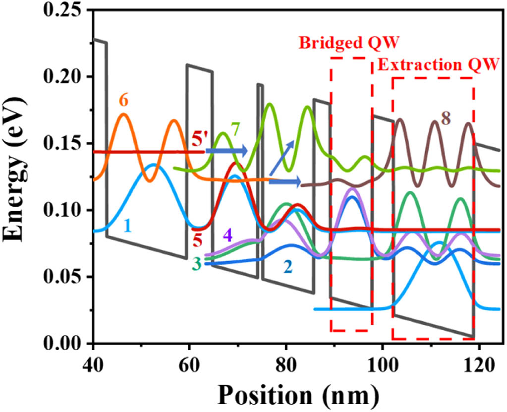
Figure 1.Schematic conduction band diagram of one module of the four-quantum-wells active region under an applied electric field of .
For THz QCLs, metal-stripe buried grating is a simple and effective way to obtain precise frequency control and robust single-mode operation through an effective refractive index modulation by patterning the grating into the active region [23,24]. Furthermore, due to the small confinement factor (0.1–0.5) of the THz QCLs with semi-insulating surface-plasmon (SISP) waveguide [17], mode selection for edge-emitting devices is generally achieved by first-order DFB gratings. However, for the uniform grating designs, the optical field is accumulated in the center of the laser cavity because of the over-coupled feedback mechanism [25], and a sampled grating technology was adopted to enhance the output powers of THz DFB QCLs [24] and mid-infrared QCLs [26,27] by regulating the optical coupling strength. In order to improve the optical powers of the front facet while ensuring the single-mode performance and avoiding catastrophic failure of the high-reflectivity (HR) coating on the rear facet, we adopted a graded sampled grating (SG) design to engineer light intensity distribution by controlling both the field distribution and coupling coefficient; thus, the longitudinal spatial hole-burning and the degeneration of the yield are overcome. The period of the sampled grating can be expressed as where is the period of the seed grating, is the grating order, is the Bragg wavelength, is the effective refractive index, is the wavelength of st order supermodes, and is the period of the sampled grating. The schematic diagram of the graded sampled grating DFB QCL and images taken with a 3D stereomicroscope are presented in Figs. 2(a) and 2(d). Here, the seed grating period μ with a duty cycle of was selected, and we chose the sampled grating period of μ to obtain a reliable single-mode operation, while the sampling duty cycle () of the graded sampled grating gradually varies from 0.9 to 0.3 along the cavity. The front facet with a duty cycle of 0.3 can be regarded as a lower reflectivity mirror due to a lower coupling coefficient, while the rear facet with a duty cycle of 0.9 is equivalent to a mirror with higher reflectivity. With these parameters, we simulated the mode distribution of uniform grating, sampled grating, and graded sampled grating via the two-dimensional finite element method. Figure 2(b) depicts the calculated mode loss for different modes of the graded sampled grating. A is the desired mode that has a lower mode loss. Normalized mode intensity distributions ) along the laser cavity of the three grating configurations are shown in Fig. 2(c). Most of the optical field inside the uniform grating is localized in the center of the laser cavity due to its over-coupled mechanism. The output powers of the front and rear facets are enhanced by lowering the effective coupling coefficient of the sampled grating laser, while the graded sampled grating laser increases the output power of the front facet even further by decreasing the sampling duty cycle toward the front facet. For the graded sampled laser, the intensity of the light field at the front facet is approximately twice that of the rear facet.
Figure 2.(a) Schematic diagram of the graded sampled grating DFB QCL. (b) Calculated mode loss versus wavelength for the QCL with graded sampled grating. (c) The envelope distribution of mode intensities () inside lasers with three different grating structures. (d) The top view images of the DFB QCL structure and one-period sampled grating taken with a 3D stereomicroscope and one-period sampled grating.
The QCL structure was grown by molecular beam epitaxy on a semi-insulating GaAs substrate, with an 11 μm thick active region (180 cascade modules) sandwiched by an Si doped top contact layer (100 nm) and a 500 nm thick n-GaAs bottom contact layer Si-doped with a density of . The wafers were processed into ridges with widths of 250 μm and 150 μm via conventional photolithography and wet chemical etching techniques. For the DFB QCLs, the graded sampled grating was etched on the top of the active region with an etching depth of 400 nm. Two Ge/Au/Ni/Au stripes were deposited on the highly doped upper layer to form ohmic contact, and the uncovered absorbing edge can suppress higher-order transverse modes. The Ti/Au layer was then evaporated on the top of the ridge and the bottom contact layer. Finally, the substrate was thinned to 120 μm to improve heat dissipation. The processed wafer was cleaved into devices with different cavity lengths with the front and rear facets uncoated, and the devices were indium soldered and wire-bonded on copper submounts.
For sample characterization, FP QCLs and DFB QCLs with graded sampled grating structures were fabricated, based on SISP waveguides. Copper submounts with lasers were mounted on a cold plate in a liquid-helium cryostat with 3 mm thick TPX (4-polyethylene-1) windows. The optical powers were collected by a thermopile detector (Ophir 3A-P-THz) calibrated by Thomas Keating absolute power meter and corrected for the TPX window transmittance of 78%. The emission spectra were measured using a Fourier-transform infrared spectrometer (Bruker, Vertex 80v).
Sign up for Photonics Research TOC. Get the latest issue of Photonics Research delivered right to you!Sign up now
4. RESULTS AND DISCUSSION
Figure 3(a) shows the typical light-current-voltage (L-I-V) characteristics for FP devices from front facets with various dimensions at 8 K. The devices operated in pulsed mode and rectangular pulses of 10 μs duration repeated at 1 kHz were used for biasing. Low threshold current densities ( are approximately between ) were observed in these devices, which are much lower than that in Refs. [12,18,19]. This is a direct consequence of reduced parasitic and leakage currents in our design, as discussed in the active region design section. According to Ref. [15], the parasitic current density () corresponds to a nonradiative electron transport process based on resonant tunneling and optical phonon emission. The I-V characteristics suggest that there is a existing between the voltage point and the initial alignment point, as shown in Fig. 3(c). Thus, the experimental of these devices are between , determined by I-V characteristics at the points where the differential resistance is locally maximal [15]. At 8 K, a peak output power of 220 mW was emitted by a device with a dimension of . We extract the waveguide loss by comparing the acquired between lasers with different cavity lengths. Note that such a high waveguide loss is directly related to the strong optical absorption near the reststrahlen band to the emitting frequencies. The temperature-dependent L-I-V characteristics of this device are shown in Fig. 3(b). A maximum operating temperature of 100 K is obtained. A representative spectrum at 8 K is also shown in the inset. Figure 3(c) depicts the CW L-I-V characteristics of the device with a ridge width of 150 μm and a cavity length of 2 mm at different heat sink temperatures, while Fig. 3(d) shows the lasing spectra from the device at different injection currents at 15 K. A maximum CW optical power of 79 mW at 15 K is achieved. The device exhibits multimode spectra and broadening toward high frequencies with increasing injection current, where the highest emitting frequency at high currents reaches up to 5.26 THz.
Figure 3.(a) Light peak output power-current-voltage (L-I-V) characteristics of the FP lasers of various dimensions at 8 K. (b) Temperature-dependent L-I-V characteristics in pulsed mode of the FP laser with dimensions . (c) Temperature-dependent L-I-V characteristics in CW mode of the FP QCL with dimensions . (d) Emission spectra of the device shown in (c) at various injection current densities.
Figure 4 illustrates the performance for single-mode CW operation of the DFB QCL with graded sampled grating and a dimension of As the L-I-V curves depicted in Fig. 4(a), lasing started with a low of while the operating voltage lay between 11 and 13.1 V at 15 K. The maximum optical power of was obtained when the current density reached . The maximum operating temperature of the laser is 45 K, which can be explained by the following reasons. The energy spacing of 19.2 meV between the upper level 5 and lower level 4 results in smaller kinetic energy of electrons that leads to a significant decrease in the lifetime of the upper level at elevated temperature through Fröhlich interaction, and the poor heat dissipation of the SISP waveguide structure is not conducive to high-temperature operation. A stable single-mode operation at various temperatures is presented in Fig. 4(b), where the device emitted at the frequency of 5.13 THz with an SMSR above 24 dB.
Figure 4.(a) CW L-I-V curves of DFB QCL with the dimensions at various heat sink temperatures. (b) The corresponding emission spectra at various heat sink temperatures for an injection current of 0.95 A.
The high optical loss for the high-frequency THz DFB QCLs limits the power extraction efficiency for the devices, as shown in Fig. 5(a). The power stays almost the same for the DFB devices with and without HR coatings. This indicates that HR coating is not an effective way to improve the power output of the DFB devices. The reason is that the high loss and strong DFB coupling reduce the portion of the power emitted from the cavity. By using graded SG DFB devices to engineer the internal field distribution along the cavity, the power extraction efficiency is greatly enhanced by about a factor of 2, as shown in Fig. 5(a). It is clear that the graded sampled grating significantly improves the THz power and outcoupling efficiency compared with the DFB QCLs with or without HR coating. To further consolidate this finding, we collected and compared the optical powers of the front and rear facets of 12 DFB QCLs with graded sampled grating. The lasers operated in pulsed mode with a 1% duty cycle at a repetition frequency of 5 kHz. Figure 5(b) displays the peak optical powers and ratio between the front and the rear facets in bars and points, respectively. Although the output power of each DFB QCL varies, the power ratio between the front and rear facets is approximately 2 for all devices, indicating that the output power at the front facet of the DFB QCL is effectively enhanced via graded sampled grating, as we expected.
Figure 5.(a) Output powers of coated and uncoated devices with uniform grating and device with graded sampled grating. (b) The optical powers and ratio between the front and the rear facets of 12 graded sampled DFB QCLs and five uniform grating DFB QCLs with the dimension of .
In conclusion, based on a detailed design optimization we have demonstrated the first CW operation of multimode FP THz QCLs with a maximum lasing frequency of 5.26 THz and the first single-mode CW operation of DFB QCLs emitting at the frequency of 5.13 THz. The maximum peak optical power of the FP QCLs is 220 mW at 8 K in pulsed mode, while the maximum single-mode optical power of 48 mW with an SMSR of 24 dB is obtained from the graded sampled DFB QCLs in CW mode at 15 K. The graded sampled DFB grating also exhibits an improved power outcoupling efficiency by a factor of 2 from the front facet compared with the uniform grating device. By further design and optimization of the active region, it is feasible to achieve single-mode THz QCLs at even higher frequencies with engineered field distribution using the graded sampled grating design.
Acknowledgment
Acknowledgment. We would like to thank Ping Liang and Fengmin Cheng for their help in the device processing.
[4] P. Tewari, Z. D. Taylor, D. Bennett, R. S. Singh, M. O. Culjat, C. P. Kealey, J. P. Hubschman, S. White, A. Cochran, E. R. Brown, W. S. Grundfest. Terahertz imaging of biological tissues. Stud. Health Technol. Inf., 163, 653-657(2011).
[12] L. H. Li, I. Kundu, P. Dean, E. H. Linfield, A. G. Davies. High-power GaAs/AlGaAs quantum cascade lasers with emission in the frequency range 4.7–5.6 THz. International Quantum Cascade Lasers School and Workshop(2016).