
Dezhen Yang, Songlin Yu, Jinjun Feng. Dynamic real-time restoration algorithm of defective pixels based on spatio-temporal statistics feature[J]. Infrared and Laser Engineering, 2022, 51(3): 20210798
- Infrared and Laser Engineering
- Vol. 51, Issue 3, 20210798 (2022)
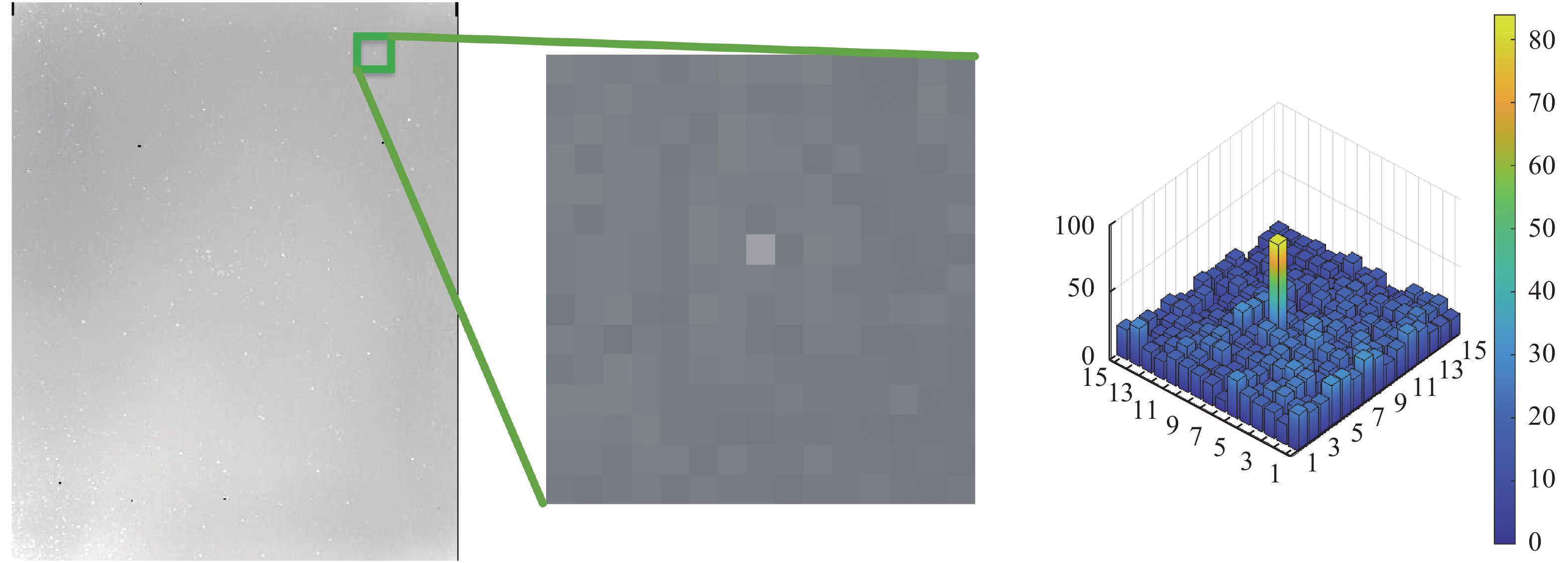
Fig. 1. Blind element 15×15 neighborhood gray distribution on clean background
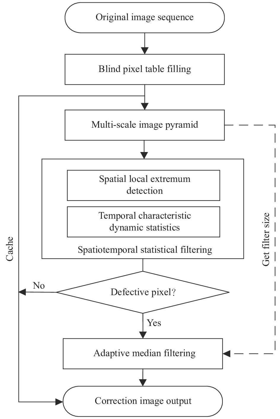
Fig. 2. Flow chart of the proposed algorithm
Fig. 3. Local extremum operator
Fig. 4. Defective pixel location based on extremum operator and three-layer pyramid
Fig. 5. FPGA logic implementation flow of the proposed algorithm
Fig. 6. Timing simulation result of hardware implementation
Fig. 7. Target and defect element sequence set in multiple scenarios
Fig. 8. Comparison of FPGA implementation using different methods. (a) Original image output by the detector; (b) Multi-scale adaptive median filter; (c) Local contrast method based on saliency; (d) Structural elements and 3σ criterion; (e) Proposed algorithm
Fig. 9. Diagram of the performance improvement for point target detection. (a) Multiscene infrared point target detection; (b) Target neighborhood; (c) 3 D image of grayscale distribution of point target neighborhood; (d) Target neighborhood with the proposed algorithm; (e) 3 D image of the grayscale distribution of point target neighborhood with the proposed algorithm
|
Table 1. Comparison of temporal and spatial gray distribution characteristics of defect element, target and clean background
|
Table 2. Comparison of BSF of different algorithms
|
Table 3. Effects and problems of different algorithms for eliminating isolated pixel, flickering pixel and defective pixel clusterss
| |||||||||||||||||||||||||||||||||||||||||||||||||||||||||||||||||||||||||||||||||||||||||||||||||||||||||||
Table 4. Comparison of detection performance of different algorithms in three kinds of scenes

Set citation alerts for the article
Please enter your email address
© Copyright 2018-2021 | Chinese Laser Press. All Rights Reserved 沪ICP备15018463号-20