• Chinese Optics Letters
  • Vol. 22, Issue 2, 022703 (2024)
Wenqi Li, Qiqi Deng, Xueshi Guo*, and Xiaoying Li**
Author Affiliations
  • College of Precision Instrument and Opto-Electronics Engineering, Key Laboratory of Opto-Electronics Information Technology, Ministry of Education, Tianjin University, Tianjin 300072, China
  • show less
    DOI: 10.3788/COL202422.022703 Cite this Article Set citation alerts
    Wenqi Li, Qiqi Deng, Xueshi Guo, Xiaoying Li. Acousto-optic modulator-based bi-frequency interferometer for quantum technology[J]. Chinese Optics Letters, 2024, 22(2): 022703 Copy Citation Text show less
    (a) Optical frequency-shifting and interference property when an AOM is used as a bi-frequency beam splitter/combiner. (b) ABI whose output ports preserve the optical frequency at the output ports.
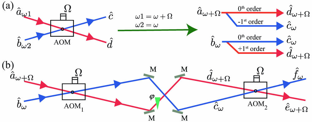
    Fig. 1. (a) Optical frequency-shifting and interference property when an AOM is used as a bi-frequency beam splitter/combiner. (b) ABI whose output ports preserve the optical frequency at the output ports.
    Three typical functions fulfilled by the ABI. (a) Bi-frequency beam splitter with variable splitting ratio; (b) frequency tuner of quantum state; (c) optical switch controlled by gating the RF driving signal to have the AOMs chopped.
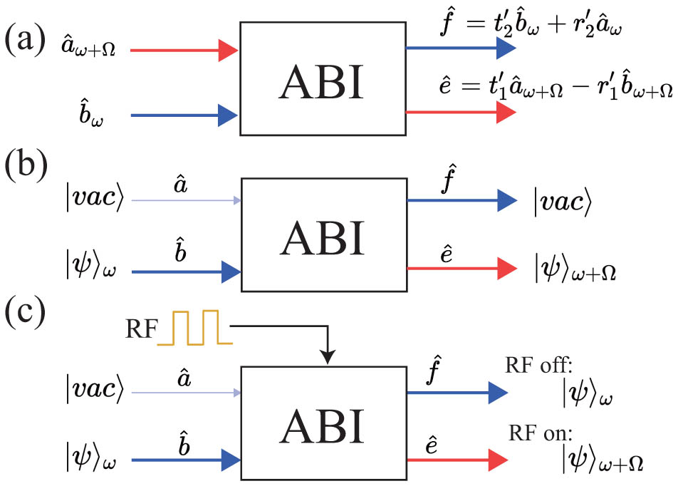
    Fig. 2. Three typical functions fulfilled by the ABI. (a) Bi-frequency beam splitter with variable splitting ratio; (b) frequency tuner of quantum state; (c) optical switch controlled by gating the RF driving signal to have the AOMs chopped.
    (a) Experimental setup of the ABI. AOM, acousto-optic modulator; CM, concave mirror; PZT, piezo-electric translation device; PD, photodiode; SPD, single-photon detector; DAQ, data acquisition system. (b) 100 kHz beating signal detected by PD1 from the light with microwatt level intensity; (c) 5 Hz beating signal detected with SPD from the light with single-photon level intensity. Red dashed-dotted lines in (b) and (c) are the fitting to the data.
    Fig. 3. (a) Experimental setup of the ABI. AOM, acousto-optic modulator; CM, concave mirror; PZT, piezo-electric translation device; PD, photodiode; SPD, single-photon detector; DAQ, data acquisition system. (b) 100 kHz beating signal detected by PD1 from the light with microwatt level intensity; (c) 5 Hz beating signal detected with SPD from the light with single-photon level intensity. Red dashed-dotted lines in (b) and (c) are the fitting to the data.
    (a) Output intensity of an ABI without beating detected by PD1 for PZT scanned (blue), locked to maximum (green), and locked to minimum (orange); (b) AOM driving signal RF1 and RF2 to realize phase dithering for the phase-locking scheme. Both RF1 and RF2 are centered at 80 MHz. The modulation for phase locking of the ABI is realized by adding a 200 kHz small signal phase modulation to RF1. For illustration purposes, the upper trace is plotted with larger modulation strength and frequency than that used in the experiment.
    Fig. 4. (a) Output intensity of an ABI without beating detected by PD1 for PZT scanned (blue), locked to maximum (green), and locked to minimum (orange); (b) AOM driving signal RF1 and RF2 to realize phase dithering for the phase-locking scheme. Both RF1 and RF2 are centered at 80 MHz. The modulation for phase locking of the ABI is realized by adding a 200 kHz small signal phase modulation to RF1. For illustration purposes, the upper trace is plotted with larger modulation strength and frequency than that used in the experiment.
    (a) Output intensity in switch mode detected by PD1 with a locking duty cycle of 30%; in this mode, the AOM driving signals RF1(2) are turned on and off periodically by a gate signal shown above the intensity result. (b) SPD counting result of the ABI in frequency tuner mode with a detection duty cycle of 50%. The error bar for counting results is the same size or smaller than the data point. The input light is a temporally complementary pattern of an LR light with intensity on the microwatt level and a weak Coh with intensity on the single-photon level. The timing sequences of LR and Coh are shown above the counting result. SPDe, SPD trigger-enabled signal.
    Fig. 5. (a) Output intensity in switch mode detected by PD1 with a locking duty cycle of 30%; in this mode, the AOM driving signals RF1(2) are turned on and off periodically by a gate signal shown above the intensity result. (b) SPD counting result of the ABI in frequency tuner mode with a detection duty cycle of 50%. The error bar for counting results is the same size or smaller than the data point. The input light is a temporally complementary pattern of an LR light with intensity on the microwatt level and a weak Coh with intensity on the single-photon level. The timing sequences of LR and Coh are shown above the counting result. SPDe, SPD trigger-enabled signal.
    Wenqi Li, Qiqi Deng, Xueshi Guo, Xiaoying Li. Acousto-optic modulator-based bi-frequency interferometer for quantum technology[J]. Chinese Optics Letters, 2024, 22(2): 022703
    Download Citation