College of Precision Instrument and Opto-Electronics Engineering, Key Laboratory of Opto-Electronics Information Technology, Ministry of Education, Tianjin University, Tianjin 300072, China
【AIGC One Sentence Reading】:We've created a high-performance interferometer using acousto-optic modulators, achieving high visibility and efficiency. With active phase stabilization, it offers beating or beating-free interference for single-photon quantum states, enabling coherent combination, frequency tuning, and optical switching for advanced quantum applications.
【AIGC Short Abstract】:We've developed a high-performance bi-frequency interferometer using acousto-optic modulators. It achieves beating or beating-free interference for single-photon quantum states, with high visibility and optical efficiency. The interferometer's phase is stabilized via a dithering phase-locking method. We showcase its applications in quantum technology, such as coherent combination, frequency tuning, and optical switching, highlighting its versatility for various quantum tasks.
Note: This section is automatically generated by AI . The website and platform operators shall not be liable for any commercial or legal consequences arising from your use of AI generated content on this website. Please be aware of this.
Abstract
We demonstrate a high-performance acousto-optic modulator-based bi-frequency interferometer, which can realize either beating or beating free interference for a single-photon level quantum state. Visibility and optical efficiency of the interferometer are and , respectively. The phase of the interferometer is actively stabilized by using a dithering phase-locking scheme, where the phase dithering is realized by directly driving the acousto-optic modulators with a specially designed electronic signal. We further demonstrate applications of the interferometer in quantum technology, including bi-frequency coherent combination, frequency tuning, and optical switching. These results show the interferometer is a versatile device for multiple quantum technologies.
Making use of the acousto-optic Bragg diffraction effect, acousto-optic modulators (AOMs) are versatile active optical devices that can efficiently change both the frequency and the propagating direction of an optical field in real time[1]. AOMs have been used in various applications, such as stabilizing output power, reducing linewidth, and shaping the spatial profile of a laser beam.[2–4]. AOMs can be exploited to realize active optical tweezers and ultrashort pulse picking[5,6]. In addition to the aforementioned applications in classical technology, AOMs are also indispensable for many quantum technologies. Taking advantage of switching with high isolation, they have been used in photon subtraction-based non-Gaussian state generation[7,8], photon-triggered homodyne tomography[9], or controlling of quantum memory[10]. Taking advantage of introducing frequency shifting to an optical field, they are used to implement optical heterodyning[11,12], to observe a beating signal from single photons[13], or to generate a phase-locking reference without displacing the quantum state[14]. Currently, the maximum diffraction efficiency of commercially available AOMs is around 85%, which reduces as the bandwidth of AOM increases, and a harsh requirement on the input beam size and driving power has to be fulfilled in order to achieve this efficiency. While the efficiency is enough for most classical applications, it is still not high enough for quantum applications where quantum states have to transmit through the AOMs and keep high purity. This impels us to consider the interferometric enhancement of the diffraction effect when using AOMs in quantum technology.
In most application schemes of AOMs, only one output port (either the direct pass beam or the diffracted beam) is used and the other is abandoned[15,16]. However, AOMs are apparently four-port devices that can be used for bi-frequency beam splitting. Recently, AOM has been used as a beam splitter to implement photon heterodyning[12]. More recently, AOM-based interferometers have been used to observe the beating signal of single photons[13] or bidirectional routing laser pulses[17], where both beam-splitting and beam-combining functions are carried out by AOMs. The visibility of the beating signal in Ref. [13] is only about 15%, far from the ideal value of 1. Moreover, both experiments make use of co-propagation optical configuration and create either slow beating of about 1 kHz[13] or a fast beating signal of about 200 MHz[17]. On one hand, this co-propagation setup and scanning effect of beating signal will reduce the influence of phase drifting and make active phase stabilizing less important. On the other hand, beating free and spatially separated interference can be necessary in many application schemes. Here we demonstrate an AOM-based bi-frequency interferometer (ABI) working in chopped phase-locking[18] mode that can realize either beating or beating free interference for a single-photon-level quantum state. By carefully designing the optical system and optimizing the mode matching, the visibility of the beating signal is . We also carefully optimize the optical transmission efficiency of the system. Especially, with specially designed driving signal for the AOM, the modulation for phase locking[19] is carried out with the same AOM for beam splitting. This simplifies the optical setup and further enhances the efficiency of the system. Moreover, we propose the application of the interferometer in quantum technology, including bi-frequency coherent combination, frequency tuning, and optical switching. With the support of experimental testing, we show these applications schemes can in principle achieve near-perfect efficiency, while only about 50% diffraction efficiency is needed for the AOMs. This property will merit many applications because it can greatly reduce the demand for AOM driving and therefore enhance the bandwidth of the system. These characteristics make the interferometer a powerful tool for many quantum technologies.
2. Working Principle of the ABI
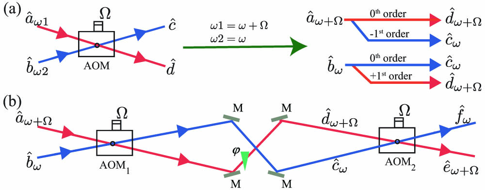
We first illustrate the working principle of the ABI. As shown in Fig. 1(a), without loss of generality, we assume two optical fields, and , are aligned to the and the order Bragg diffraction of an AOM, and the output fields and have the form of[13]where and denote the spatial modes and in the subscripts denotes their optical frequency. After passing the AOM, the optical frequency is up/downshifted by the frequency of the radio frequency (RF) signal . , satisfying are the real number transmission and reflection parameters determined by the strength of the RF signal, and is the diffraction efficiency of the AOM. is an AOM-induced phase decided by the phase of the RF signal. Each field operator in Eq. (1) satisfies the standard bosonic commutation relation; for example, has the commutation relation .
Sign up for Chinese Optics Letters TOC. Get the latest issue of Chinese Optics Letters delivered right to you!Sign up now
Figure 1.(a) Optical frequency-shifting and interference property when an AOM is used as a bi-frequency beam splitter/combiner. (b) ABI whose output ports preserve the optical frequency at the output ports.
Assuming the frequencies of ports and are and , the output ports and only contain the optical field with frequency of and , respectively. Therefore, and interfere at and and can be coherently combined by using another AOM to form a bi-frequency Mach–Zehnder interferometer, as shown in Fig. 1(b). The output fields of the interferometer can be obtained by using Eq. (1) twice, with
These effective coefficients are decided by the optical path-induced phase difference , the AOM splitting parameters , , and the AOM driving-induced phase for and , respectively.
Assume we send light from port and detect it from port in Fig. 1(b). Then when the input light is a coherent state and and are set to , the intensity at can be obtained by using Eq. (2), where is the overall phase parameter of the interferometer, is the intensity of the input light. Equation (4) describes the ABI under ideal conditions. In practice, there inevitably exist three imperfections: (i) the nonideal efficiency of the optical components; (ii) the nonideal mode matching between the two arms of the interferometer; and (iii) the frequency difference between the two RF driving signals. With these factors considered, Eq. (4) is rewritten as where is the efficiency determined by the losses of the optical elements in ABI, is the mode mismatching-induced visibility of the interference, and is the beating term induced by the frequency difference of the RF signals that drive the two AOMs.
3. Applications in Quantum Technology
To show the ABI with high efficiency and high visibility is a very useful tool for quantum technology, we analyze three typical functions that can be implemented by using ABI (see Fig. 2). As shown in Fig. 2(a), the ABI can be applied to coherently combine two quantum states with slightly different frequencies. From Eqs. (2) and (3), one sees the ABI can achieve an arbitrary effective splitting ratio and when the maximum diffraction efficiency of each AOM can reach 50% and the phase parameters , , and are well controlled. Since frequency is one of the important degrees of freedom for the optical mode[20], this scheme can be used to create continuous variable Einstein–Podolsky–Rosen state out of two single-mode squeezing states with frequency difference or creating a large-scale entangled state with multiple pairs of frequency-encoded two-mode entangled states[21–23].
Figure 2.Three typical functions fulfilled by the ABI. (a) Bi-frequency beam splitter with variable splitting ratio; (b) frequency tuner of quantum state; (c) optical switch controlled by gating the RF driving signal to have the AOMs chopped.
The scheme in Fig. 2(a) can make two quantum states with different frequencies interfere. By slightly modifying the scheme [see Fig. 2(b)], the ABI can realize a frequency tuner scheme for quantum states, which can tune the frequency of a quantum optical state and fit that of the other quantum system[10,24]. In this scheme, a quantum state is sent in at port, and the port is reserved for vacuum input. According to Eqs. (1)–(4), by controlling the overall phase parameter of the ABI to , the quantum state will be shifted by in optical frequency and output at port, where is used to denote the output state with frequency shifted. In this ideal case, the state at port is a vacuum state. Since this frequency shift is controlled by the frequency of the RF signal, it provides us with a handy tool to realize quantum state frequency tuning.
If we control the overall phase parameter of the ABI to and in Fig. 2(b), the input state will go to port with a frequency shift and port without a frequency shift, respectively. Therefore, the ABI can also be used as an optical switch. However, in this scheme, both the isolation and the transmission efficiency of the switch are confined by the visibility of the interference. In quantum technologies, AOM-based switches are often used as a protection stage before a weak light detection process[7,9], and good isolation is a critical requirement for such a switch. To solve this problem, we propose the optical switch scheme in Fig. 2(c), where a high-isolation property is achieved by adding a gate to the RF signals that drive the AOMs. When the RF signals are off, the optical path of the interferometer is degraded into two independently propagated spatial modes. With the same input configuration as Fig. 2(b), the input state will go to port when the RF signal is off and the isolation between and ports is high. When the RF signal is on, we are able to set the effective transmission/reflection coefficients to and by controlling the overall phase . In this case, the quantum optical state is transmitted to port with frequency upshifted.
We note all the three schemes in Fig. 2 can also be implemented with a single AOM. However, benefiting from the interferometric enhancement of the diffraction effect, our scheme can achieve a near-perfect efficiency when each AOM is working at around 50% diffraction efficiency. This enhancement is critical in many quantum application schemes, especially for those using continuous variable quantum states.
4. Experimental Demonstration of the ABI
Our experimental setup for the ABI is shown in Fig. 3(a). A linearly polarized continuous-wave (CW) laser beam with a wavelength of 1550 nm is coupled to the mode [ in Fig. 1(b)] of the AOMs (ISOMET M1205) with a fiber collimator (FC). The beam is split into a frequency upshifted arm (red beam with the frequency of ) and a nonshifted arm (blue beam with the frequency of ) by . The two beams are then coherently combined by . For each arm between the two AOMs, two plane mirrors and a concave mirror with 300 mm radius of curvature are used to ensure the required mode matching is optimized. To control the phase between two arms, a piezo device (PZT) is mounted on the concave mirror of the frequency-shifted arm. At the output of the , the frequency upshifted port is detected by a power detector, which is either a photon diode () for measuring intensity with higher photon number or a single-photon detector (SPD, id Quantique-id200) for intensity at the single-photon level. The output of the frequency nonshifted port is detected with . Detection results for both and are sent to a field programmable gate array (FPGA)-based (STEMlab125-14) data acquisition system (DAQ), which also generates the feedback signal to the PZT for phase locking.
Figure 3.(a) Experimental setup of the ABI. AOM, acousto-optic modulator; CM, concave mirror; PZT, piezo-electric translation device; PD, photodiode; SPD, single-photon detector; DAQ, data acquisition system. (b) 100 kHz beating signal detected by PD1 from the light with microwatt level intensity; (c) 5 Hz beating signal detected with SPD from the light with single-photon level intensity. Red dashed-dotted lines in (b) and (c) are the fitting to the data.
We first run the setup in slow beating mode, where the active phase stabilizing is off and no signal is added on the PZT. In this mode, we demonstrate the bi-frequency property by the beating effect and use the beat result to calibrate the visibility and the transmitting efficiency of the system. and driving the AOMs are generated by a two-channel arbitrary function generator (Siglent-SDG2122X) and are set to 80 and 79.9 MHz. Thus the beating frequency is 100 kHz. Figure 3(b) shows a measured beating signal for the input light of microwatt level intensity, where is normalized to the intensity of input field . The blue traces are the directly measured data and the red dashed-dotted line is the fitting to Eq. (5). , , and in Eq. (5) are set to be the fitting parameters. One sees the fitting curve overlaps well with the directly measured data, and the fitting result is , , and , respectively. This result shows we realize almost perfect visibility and high optical efficiency simultaneously. We note each optical surface in our setup has a loss of about 0.5% limited by the quality of optical coating, so can be further improved once components with better optical coatings are used. We then heavily attenuate the intensity of the input light to single-photon level and detect the beating signal by replacing with the SPD, which is triggered by its internal 50 MHz clock. To get enough counts for a counting window (10 ms), the beating frequency is reduced to 5 Hz by changing the driving frequency of . The counting result and its fitting are shown in Fig. 3(c), where the detection efficiency of the SPD is about 20%, and the dark count is counts/trigger at this counting setup. Compared with the maximum counting rate of about 0.06 counts/trigger, the dark count is negligible in this measurement. Compared to the result in Fig. 3(b), which is obtained in the condition of input light at microwatt level and beating frequency of 100 kHz, data points in Fig. 3(c) obviously deviate from the fitting curve due to a larger time scale for phase drifting. However, this will not prevent us from getting the visibility, since it is only determined by the maximum and the minimum value of the curve. The fitting result shows the visibility for light with optical intensity at a single-photon level is , which is almost the same as the case for input light with higher intensity.
Second, we set and to be identical frequencies of exactly 80 MHz and scan the PZT with a 30 Hz ramp signal. The interference fringe detected by is shown by the blue trace in Fig. 4(a), where the input light is on the microwatt level. When triggered by the ramp signal, one sees the fringe moves on the oscilloscope horizontally in a random direction. This is caused by the phase drift between the two arms, and this shows it is necessary to introduce an active phase-locking scheme. We use a dithering phase-locking scheme[19] to stably lock the ABI to an arbitrary phase. As shown in Fig. 4(b), the modulation required in this phase-locking scheme is realized by adding a 200 kHz phase modulation with a small modulation depth to . Therefore, is used for both beam splitting and introducing the modulation for phase locking. This special design avoids using extra optical modulators and enhances the optical efficiency of the system. By properly configuring the FPGA system to implement digital demodulators, proportional-integral-derivative (PID) controllers, and digital filters[25], the overall phase can be locked to arbitrary value using the detection result of . The green and orange traces in Fig. 4(a) show two typical locking results when the overall phase is 0 and and the values of at port are locked to the maximum and minimum point, respectively. By comparing the beating signal, we find the visibility of interference for the identical frequency case is reduced to . Substituting the obtained from the fitting of the beating signal and this visibility into Eq. (5), we find the total transmission efficiency of the ABI when used as an optical switch is . We study the reason for this visibility reduction and find, besides a phase shift, that the PZT can cause the beam walking off and induce mode mismatching. We note that, though this work only focuses on using a PZT to introduce a phase shift, the phase shift can also be introduced by controlling the electronic phase of the RF signal that drives . Moreover, the visibility reduction problem can be in principle avoided if is directly used as the phase-shifting device of the phase-locking system. To complete this optimization, angle calculation and phase-unwrapping algorithms are necessary to be implemented in the FPGA[24], and progress is underway.
Figure 4.(a) Output intensity of an ABI without beating detected by PD1 for PZT scanned (blue), locked to maximum (green), and locked to minimum (orange); (b) AOM driving signal RF1 and RF2 to realize phase dithering for the phase-locking scheme. Both RF1 and RF2 are centered at 80 MHz. The modulation for phase locking of the ABI is realized by adding a 200 kHz small signal phase modulation to RF1. For illustration purposes, the upper trace is plotted with larger modulation strength and frequency than that used in the experiment.
In the next step, we run the setup in a chopped locking mode for a gated RF signal. In this experiment, the input light is CW with intensity on the microwatt level, but the driving signals and are gated by two voltage-controlled attenuators. This operating mode realizes the optical switch scheme in Fig. 2(c). The RF gate signal is 100 Hz in repetition rate and the duty cycle is tunable. When the gate signals are on high voltage, the whole system works the same as the ABI being locked at the maximum output. When the gate signals are low, the driving signal of the two AOMs in the ABI is completely cut off, and the injected light will go through the frequency nonshifted arm (blue beam) in Fig. 3(a), leaving the frequency-shifted arm (red beam) in high isolation state to the input field. A locking feedback-enabled signal synchronized to the RF gate signal [see the yellow waveform labeled by “Gate to ” in Fig. 5(a)] is sent to the DAQ to stop the locking process and hold the feedback value to increase the stability of the locking process. In the experiment, we gradually reduce the duty cycle of the RF signal and find the setup works well with a duty cycle as low as 30%, and a typical measured intensity result detected by is shown by the blue trace in Fig. 5(a), in which one sees the locks are stable after a locking establishing time of submillisecond order. We note the phase-locking stability increases when either the frequency or the duty cycle of the locking process increases. We further measure the isolation of the ABI when it is used as an optical switch. Since the isolation exceeds the dynamic range of the SPD, we insert calibrated optical attenuators after the FC when measuring the photon numbers for the RF on-state and remove it when measuring the RF off-state. By comparing the photon-counting results for the on- and off-states, we find the isolation is about 74 dB. This shows the setup functions as a high isolation optical switch from either input port to its double-diffracted output port. Though confined by the visibility, isolation of either input port to its double direct pass port is only around 15 dB when used as an optical switch.
Figure 5.(a) Output intensity in switch mode detected by PD1 with a locking duty cycle of 30%; in this mode, the AOM driving signals RF1(2) are turned on and off periodically by a gate signal shown above the intensity result. (b) SPD counting result of the ABI in frequency tuner mode with a detection duty cycle of 50%. The error bar for counting results is the same size or smaller than the data point. The input light is a temporally complementary pattern of an LR light with intensity on the microwatt level and a weak Coh with intensity on the single-photon level. The timing sequences of LR and Coh are shown above the counting result. SPDe, SPD trigger-enabled signal.
Finally, we run the setup in a chopped phase-locking mode for a temporally complementary input of a locking reference (LR) light and a weakly coherent light (Coh). The high extinction ratio of between LR and Coh is ensured by using two mechanical fiber optical switches (e-Photics YFS-), which prevent the SPD from counting the photons in LR. This mode realizes the frequency tuner scheme in Fig. 2(b) for a weak input state. The waveform at the top of Fig. 5(b) shows the timing sequence of this mode, where the microwatt level LR is on for 30% of the time and has a frequency of 5 Hz. LR is detected at the frequency nonshifted output port by and generates a feedback signal for phase locking, which is also enabled by a locking feedback-enabled signal synchronized to the LR. When the LR is off, the feedback signal is on hold, and the RF signals continue to drive the AOMs. Coh with a intensity on the single-photon level is used as input to simulate a quantum state and is detected at the frequency upshifted port by the SPD. To avoid saturating the SPD, we only enable the SPD using a gate with 50% duty cycle by using an SPD-enabled signal, SPDe. Data points in Fig. 5(b) show the counting result with a counting window of 20 ms, where one sees the counting rate stability follows the shape of the SPDe signal. This result shows our ABI can work in a chopped locking scheme for single-photon level input.
5. Summary
In summary, we experimentally realize an ABI. The interference visibility of the beating signal of the ABI is , and the optical efficiency is . Benefiting from the interferometric enhancement of the diffraction effect, the interferometer can realize multiple quantum technologies with high efficiency such as bi-frequency coherent combining, optical switching, and frequency tuning. The interferometer can work in chopped locking mode, which enables the operating of light with intensity on the single-photon level. With a specially designed RF driving signal, the modulation for phase locking is implemented on the beam-splitting AOM, which reduces the number of optical elements and increases the overall quantum efficiency. The performance of the experimental system we realized is currently confined by the optical loss of the components and the beam walk-off induced by the PZT. With the high visibility of the beating signal, we believe the overall efficiency to implement optical switching or coherently combine quantum states with the ABI can be further improved to around 98%–99% by using commercially available ultralow-loss optical components.
References
[1] G. Wade. Bulk-Wave Acousto-Optic Bragg Diffraction, 11(1990).
[25] L. Neuhaus, R. Metzdorff, S. Chua et al. PyRPL (Python Red Pitaya Lockbox): an open-source software package for FPGA-controlled quantum optics experiments. Conference on Lasers and Electro-Optics Europe & European Quantum Electronics Conference (CLEO/Europe-EQEC), 1(2017).
 AI Video Guide
  AI Picture Guide
 AI One Sentence