
Cheng Li, Shengmei Zhao, "Efficient separating orbital angular momentum mode with radial varying phase," Photonics Res. 5, 267 (2017)
- Photonics Research
- Vol. 5, Issue 4, 267 (2017)
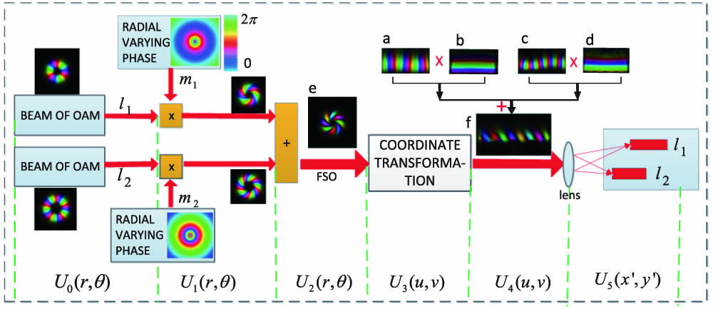
Fig. 1. OAM separation method with radial varying phase. U 0 ( r , θ ) , … , U 5 ( x ′ , y ′ ) l 1 , l 2 m 1 , m 2 e f e a c b d
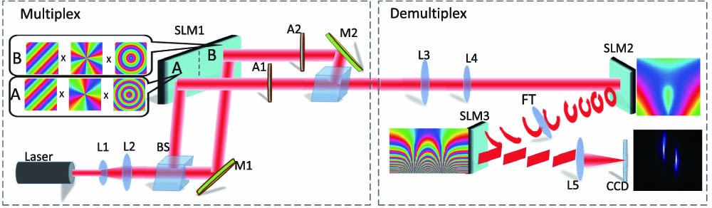
Fig. 2. Schematic setup for the experiment. L1–L5, lenses; BS, beam splitter; M1 and M2, mirrors; A1 and A2, apertures.
Fig. 3. Demonstration of the propagation properties of the radial varying phase.
Fig. 4. Simulation and experimental results for the proposed separation method with two OAM modes.
Fig. 5. Simulation and experimental results for the proposed separation method with three OAM modes.


Set citation alerts for the article
Please enter your email address

© Copyright 2018-2021 | Chinese Laser Press. All Rights Reserved 沪ICP备15018463号-20