Abstract
It is shown that orbital angular momentum (OAM) is a promising new resource in future classical and quantum communications. However, the separation of OAM modes is still a big challenge. In this paper, we propose a simple and efficient separation method with a radial varying phase. In the method, specific radial varying phases are designed and modulated for different OAM modes. The resultant beam is focused to the spots with different horizontal and vertical positions after a convex lens, when the coordinate transformation, including two optical elements with coordinate transformation phase and correct phase, operates on the received beam. The horizontal position of the spot is determined by the vortex phases, and the vertical position of the spot is dependent on the radial varying phases. The simulation and experimental results show that the proposed method is feasible both for separation of two OAM modes and separation of three OAM modes. The proposed separation method is available in principle for any neighboring OAM modes because the radial varying phase is controlled. Additionally, no extra instruments are introduced, and there is no diffraction and narrowing process limitation for the separation.1. INTRODUCTION
Recently, considerable attention has been paid to orbital angular momentum (OAM) modes because of the dramatic increase of information capacity for optical communication [1,2] and the potential of increased bandwidth for quantum cryptography [3]. It has been demonstrated that the information transmission rate can even increase to more than 100 Tb/s by multiplexing with 12 OAM modes, two polarizations, and 42 wavelengths [4]. The efficient separation of OAM modes plays an important role in OAM applications.
The simplest method for measuring the OAM content of a beam is to perform a series of projection measurements [1,5], where an OAM mode with topological charge is first transferred to a flat phase beam by being illuminated on a forked hologram with and then detected by a power detector [6,7]. Later, Leach et al. presented a technique for separating OAM modes by using a Mach–Zehnder interferometer at the single-photon level [8]. To efficiently sort OAM modes simultaneously, Berkhout et al. proposed a separating method based on the transformation from Cartesian to log-polar [9]. In addition, simulations and experiments have demonstrated that the separating method has distinguished different OAM modes simultaneously with a detector array [10,11]. Mirhosseini et al. presented a better OAM separation method with a fan-out technique to overcome the diffraction limitation [12]. Lavery et al. measure an OAM spectrum that distributes in both the horizontal and vertical dimensions by changing the radial of a beam [13]. However, the separation of OAM mode is still challenging; there is yet no method as easy as the separation of two polarization modes.
In this paper, we propose a highly efficient separation of OAM modes method with radial varying phase. A special radial varying phase is designed and added for each separated OAM mode. The coordinate transformation is afterward operated on the received beam. The received beam is unfolded, and different spots with different horizontal and vertical positions are obtained with a focused lens, where the horizontal position is determined by the vortex phases, and the vertical position is dependent on the radial varying phase. The focal spots are both separated in the horizontal and vertical dimensions; importantly, the vertical position can be controlled.
Sign up for Photonics Research TOC. Get the latest issue of Photonics Research delivered right to you!Sign up now
This paper is organized as follows. In Section 2, we describe the proposed separation method with radial varying phase. In Section 3, we present the numerical and experimental results of the proposed method. Finally, we draw a conclusion in Section 4.
2. OAM SEPARATION WITH RADIAL VARYING PHASE
The concept of the proposed method is shown in Fig. 1. The electric field of an OAM mode with topological charge is represented by where is the amplitude function of the beam, is the radial index, is waist size, and is the azimuthal index. The frame of a beam of OAM generates an OAM mode beam with a spatial light modulator (SLM). A special radial varying phase for each OAM mode is successively designed by radial varying phase and added to the OAM mode beam. Here, the radial varying phase with parameter is designed as where is a constant related to the maximum of the beam size, is the radius of the SLM size, and is the inner radius of the OAM doughnut. For simplification, is always set up to one pixel size. denotes the spatial frequency of the phase. is used for representing nonlinear property of the phase.
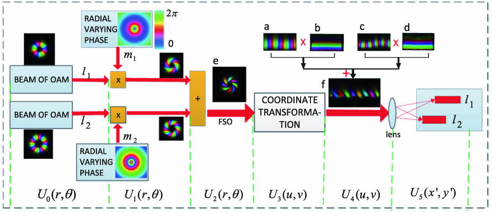
Figure 1.OAM separation method with radial varying phase. are the electric fields, denote different OAM modes, and represent different radial varying phases. Image is the superposition beam. Image is the unfolded beam from image by the coordinate transformation. FSO: free space optical channel. Images and are the horizontal distribution phases that unfolded from the vortex phases, and images and are the vertical distribution phases unfolded from the radial varying phases.
Now, the electric field of the OAM beam becomes Furthermore, the superposition of multiple OAM modes with different radial varying phases is expressed as
The superposition beam arrives at the receiver after propagating some distance in the optical free-space channel. The frame of coordinate transformation operates coordinate transformation on the receiving superposition beam, transforming the beam from Cartesian to log-polar coordinates. There are two optical phase elements, together with a Fourier lens (FT), in coordinate transformation. The first optical element has transformation phase , where ; and are scaling constants [9]. When the superposition beam passes through the first optical element followed by the FT lens, the input plane is mapped to log-polar plane , that is, where , , , and is the focal length of the FT. The position and shape of beam in the output plane is dependent on [14], where , and .
This transformation introduces some distortions, which can be corrected by the second optical element [9]. The corrected phase is expressed as . After the correction, the output electric field can be given as
In fact, Eq. (6) can be rewritten as the sum of some truncated plane waves according to the relationship between and [15]: where denotes the topological charge influencing the horizontal phase gradient in horizontal axis , and denotes the parameter influencing the vertical phase gradient in vertical axis .
After a convex lens, the unfolded beam with linear phase is focused into spots. The electric field is further described as where and denote the coordinate position in the focal plane. Since is equal to , Eq. (8) can be rewritten as where is , and is . With the property of the function , the horizontal and vertical positions of the spots can be obtained as which indicates that the spot changes as a function of and , and the position of the spot in the direction is influenced by , while the position of the spot in the direction is influenced by .
In Fig. 1, image shows the Cartesian coordinate before the transformation; image is the unfolded form of image after coordinate transformation, which can be decomposed from images to . Because the focal positions of each spot can be controlled in the vertical direction by adding a specific radial varying phase, in principle, any two spots corresponding to neighboring OAM modes can be separated.
3. SIMULATION AND EXPERIMENTAL RESULTS
In this section, we test the proposed separation method by simulation and experiment.
The experimental setup is shown in Fig. 2. The beam from an He–Ne laser source () is expanded to a collimated light by passing through lenses L1 (50 mm) and L2 (100 mm), and then is split into two beams by a beam splitter. The two beams individually illuminate one part of SLM1 (620 to 1100 nm), A and B. Each part is loaded with phases, including a vortex phase and a radial varying phase. Then two apertures, A1 and A2, are used to select the first order of the beam to propagate. The multiplexed beam propagates about 2 m in the optical free-space channel. The received beam is unfolded to a rectangle profile plane beam after illuminating SLM2, an FT and SLM3, where SLM2 is loaded with the transformation phase , and SLM3 is loaded with the correction phase . The resultant beam is focused into spots by a convex lens (L5), and a CCD is located in the focal plane of the convex lens.

Figure 2.Schematic setup for the experiment. L1–L5, lenses; BS, beam splitter; M1 and M2, mirrors; A1 and A2, apertures.
First, the property of the OAM mode with radial varying phase is demonstrated in Fig. 3. The multiplexed modes are and , where is loaded with radial varying phases, while does not have radial varying phase. When is loaded with radial varying phase, the interferogram displays the clockwise rotation for , and counterclockwise rotation for . It is shown that the multiplexed mode is controlled by the radial varying phase .
Figure 3.Demonstration of the propagation properties of the radial varying phase.
Figure 4 shows the simulation and experimental results of the proposed method with and and the average separation efficiency. Two parameters represent the radial varying phases for and , respectively. The first row denotes the results without the radial varying phases (), and the second row represents being loaded with radial varying phase and without radial varying phase. The results show focal spots are distributed in only the horizontal direction without radial varying phases, and the focal spot of is moved down in vertical direction with . The position of the focal spot is determined both by OAM topological charges and radial varying phases .
Figure 4.Simulation and experimental results for the proposed separation method with two OAM modes.
Figure 5 further demonstrates the simulation and experiment results of the proposed method for three OAM modes: , , and and their separation efficiencies. The parameters represent the radial varying phases for , respectively. In the first column, parameters of are 0. This means that there are no radial varying phases loaded on the corresponding OAM modes. Three spots are at the same horizontal positions. In the second column, only is loaded with and the spot of mode is moved down. In the third column, the spots of and are moved down when loaded with the same radial varying phases . In the fourth column, the spot of is moved up for . is kept on the original because of no radial varying phase. The results further show that the vertical position of the spot is determined by the parameter , where can be designed and controlled.
Figure 5.Simulation and experimental results for the proposed separation method with three OAM modes.
To compare with the existing separation method using coordinate transformation, Fig. 6 shows the simulation results using the methods in Refs. [9,12] and the proposed method for the neighboring modes and . The results show that the neighboring OAM modes overlap with the method in Ref. [9], the overlapping is decreased with the method in Ref. [12], and no overlapping exists with the proposed separation method. For Fig. 6(c), the radial varying phase is . If there is still some overlapping between the neighboring OAM modes, the radial varying phase for could be set to a large number to separate the two neighboring OAM modes completely. The limitation of the proposed method is that the designed varying phase should be modulated at each OAM modes at first.
Figure 6.Comparisons of the separation methods based on coordinate transformation and their corresponding separation efficiency. (a) illustrates the method in Ref. [9]; (b) illustrates the method in Ref. [12]; (c) illustrates the proposed method.
4. CONCLUSION
In this paper, we have proposed a simple and efficient OAM separation method with radial varying phase, where the radial varying phase is labeled by the parameter . OAM modes have been modulated by different radial varying phases. For the separation, the coordinate transformation has transferred the superposition OAM mode beam to spots with different horizontal and vertical positions, where the horizontal and vertical positions of the spot are determined by the OAM topological charge and the radial varying phase, respectively. The simulation and experimental results have satisfied the theoretical ones. Since the radial varying phase could be added with the same optical device as the vortex phase, the proposed method has not introduced any extra instruments. Importantly, the separation for any neighboring OAM modes is available because the radial varying phase is controlled. Furthermore, the proposed separation method provides a novel idea to avoid the diffraction limitations on OAM separation.
References
[1] J. Wang, J. Y. Yang, I. M. Fazal, N. Ahmed, Y. Yan. Terabit free-space data transmission employing orbital angular momentum multiplexing. Nat. Photonics, 6, 488-496(2012).
[2] L. Li, G. Xie, Y. Ren, N. Ahmed, H. Huang. Orbital-angular-momentum-multiplexed free-space optical communication link using transmitter lenses. Appl. Opt., 55, 2098-2103(2016).
[3] A. Vaziri, G. Weihs, A. Zeilinger. Experimental two-photon, three-dimensional entanglement for quantum communication. Phys. Rev. Lett., 89, 240401(2002).
[4] H. Huang, G. Xie, Y. Yan, N. Ahmed, Y. Ren, Y. Yue, D. Rogawski, M. J. Willner, B. I. Erkmen, K. M. Birnbaum, S. J. Dolinar, M. P. J. Lavery, M. J. Padgett, M. Tur, A. E. Willner. 100 Tbit/s free-space data link enabled by three-dimensional multiplexing of orbital angular momentum, polarization, and wavelength. Opt. Lett., 39, 197-200(2014).
[5] A. Mair, A. Vaziri, G. Weihs, A. Zeilinger. Entanglement of the orbital angular momentum states of photons. Nature, 412, 313-316(2001).
[6] G. Gibson, J. Courtial, M. J. Padgett, M. Vasnetsov, V. Pas’ko. Free-space information transfer using light beams carrying orbital angular momentum. Opt. Express, 12, 5448-5456(2004).
[7] R. Tudora, M. Mihailescuc, C. Kuskoa, I. Paunc, A. Nanc. Simultaneous and spatially separated detection of multiple orbital angular momentum states. Opt. Commun., 368, 141-149(2016).
[8] J. Leach, J. Courtial, K. Skeldon, S. M. Barnett, M. J. Padgett. Interferometric methods to measure orbital and spin, or the total angular momentum of a single photon. Phys. Rev. Lett., 92, 013601(2004).
[9] G. C. Berkhout, M. P. Lavery, J. Courtial, M. W. Beijersbergen, M. J. Padgett. Efficient sorting of orbital angular momentum states of light. Phys. Rev. Lett., 105, 153601(2010).
[10] C. Li, R. Jiang, L. Wang, S. Zhao. Simulations of high efficient separation of orbital-angular-momentum of light. J. Nanjing Univ. Post Telecommun., 36, 4752(2016).
[11] M. P. J. Lavery, D. J. Robertson, G. C. G. Berkhout, G. D. Love, M. J. Padgett. Refractive elements for the measurement of the orbital angular momentum of a single photon. Opt. Express, 20, 2110-2115(2012).
[12] M. Mirhosseini, M. Malik, Z. Shi, R. W. Boyd. Efficient separation of the orbital angular momentum eigenstates of light. Nat. Commun., 4, 2781(2013).
[13] M. P. J. Lavery, D. J. Robertson, A. Sponselli, J. Courtial. Efficient measurement of an optical orbital-angular-momentum spectrum comprising more than 50 states. New J. Phys., 15, 013024(2013).
[14] O. Bryngdahl. Geometrical transformations in optics. J. Opt. Soc. Am., 64, 1092-1099(1974).
[15] M. N. O’Sullivan, M. Mirhosseini, M. Malik, R. W. Boyd. Near perfect sorting of orbital angular momentum and angular position states of light. Opt. Express, 20, 24444-24449(2012).


