Abstract
Optical axial scanning is essential process to obtain 3D information of biological specimens. To realize optical axial scanning without moving, the tunable lens is a solution. However, the conventional tunable lenses usually induce non-uniform magnification and resolution issues. In this paper, we report a movable electrowetting optofluidic lens. Unlike the conventional tunable lens, our proposed optofluidic lens has two liquid-liquid (L-L) interfaces, which can move in the cell by an external voltage. The object distance and image distance are adjusted by shifting the L-L interface position. Therefore, the proposed lens can realize optical axial scanning with uniform magnification and resolution in microscopy. To prove the concept, we fabricate an optofluidic lens and use it in optical axial scanning. The scanning distance is more than 1 mm with uniform magnification and good imaging quality. Widespread application of such a new adaptive zoom lens is foreseeable. Introduction
3D live imaging is increasingly important in microscopy, because it provides good understanding of some biological processes. There are several methods to acquire 3D information. Among these technologies, axial scanning is the effective way to capture 3D image. The current microscopic technologies, for example, wide-field microscopy1-3, confocal microscopy4, structured illumination microscopy5 or light-sheet microscopy6, still need axial scanning to record a stack of 2D images to reconstruct 3D specimen. Various methods have been developed to realize axial scanning. One solution is performing an axial scanning of the specimen by tuning the position of the objective lens7, 8. However, it will induce non-uniform magnification and resolution issues. Besides, mechanically moving objectives fast will induce overshoots and oscillations. Another solution is using adaptive lens to adjust the effective focal length9-11. This method can realize axial scanning without any movement parts, which is an ideal way for axial scanning. For example, a method was proposed for axial scanning in confocal microscopy. By using an electrically tunable lens, axial scanning was over 250 μm without any movement parts9. However, the magnification and resolution are also changed due to the change of the focal length of the electrically tunable lens. An axial scanning method based on two electrically tunable lenses was also proposed10. It can realize fast and adaptive axial scanning. However, the performance degrades due to defocus and spherical aberrations. Optofluidic lenses11-19 and liquid-crystal lenses20, 21, which can change their focal lengths, also provide a method to realize adaptive axial scanning. However, the magnification and resolution of these methods22, 23 based on optofluidic lenses or liquid-crystal lenses are still the issues to be solved.
In this paper, we propose a movable electrowetting optofluidic lens for axial scanning in microscopy. The proposed optofluidic lens has two L-L interfaces, which can move in the cell by an external voltage. The object distance and image distance are adjusted by shifting the L-L interface position. Therefore, the proposed lens can realize optical axial scanning with uniform magnification and resolution in microscopy. To prove the concept, we fabricate an optofluidic lens and use it in optical axial scanning. The scanning distance is more than 1 mm with good imaging quality. The proposed device can be used in imaging, lighting, optical axial scanning and so on.
Schematic and principle
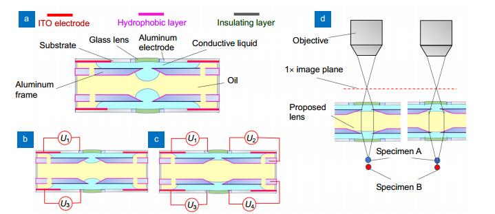
The cross-sectional cell structure and the operating mechanism of our proposed lens are depicted in Fig. 1. The proposed optofluidic lens consists of three liquid layers, as shown in Fig. 1(a). The oil is sandwiched by the conductive liquid to form two L-L interfaces. When the external voltages U1 and U3 are applied on the device, electrowetting effect happens on the substrate, which pulls the liquid outwards. Thus, the L-L interface moves downwards, as shown in Fig. 1(b). When external voltage U2 and U4 are applied on the aluminum frames, the L-L interface deforms to vary the focal length, as shown in Fig. 1(c). In our proposed lens, there are two glass lenses on the substrate. We use them for two purposes. On one hand, the two glass lenses can help to increase the optical power since the optical power of electrowetting lens is relatively limited. On the other hand, the two glass lenses are designed to correct aberrations. The working principle is shown in Fig. 1(d). The optical axial scanning system consists of two parts: the proposed lens and the microscope objective. The specimen is first imaged by our proposed lens. The first image is the same size as the specimen. Then, the first image is imaged by the microscope. The secondary image is the final image. The scanning process is as follows. The specimen A is imaged by our proposed lens. The magnification is 1×. To focus on specimen B, we just move the L-L interface to a lower position. In this way, the specimen B is on the focal point again. Thus, on the image plane, the magnification is still 1×. Then, the first image is imaged again by the microscope objective. Therefore, we can keep a constant magnification while scanning the specimen.

Figure 1.Schematic cross-sectional structure and operating mechanism of the movable electrowetting optofluidic lens.(a) Cell structure. The curvature of the silicone oil (yellow)-conductive liquid (blue) interface in the central aperture is regulated by the external voltages. (b) Moving actuation. When the external voltages U1 and U3 are applied, the L-L interface moves downwards. (c) Deforming actuation. When external voltage U2 and U4 are applied, the L-L interface deforms. (d) Working principle of axial scanning.
For our lens, the position and shape of the L-L interface are changed due to electrowetting effect. According to Young-Lippmann equation, the relationship between the contact angle θ and the applied voltage U can be described as follows:
where ε is the dielectric constant of the insulating layer, d is the thickness of the insulating layer, γ1, γ2 and γ12 are the interfacial tensions of the hydrophobic layer/silicon oil, hydrophobic layer/conductive liquid and silicon oil/conductive liquid, respectively. When we apply U1 and U3 on the device, the electrowetting effect happens, which makes the contact angle change. Thus, the L-L interfaces move towards the substrate. When U2 and U4 are applied, the contact angle at the L-L interface changes due to electrowetting effect. Therefore, the focal length of the lens is changed.
Results and discussions
Operating process
Since the proposed lens is a symmetrical structure, we first fabricate the lower part of device using transparent materials to demonstrate the moving and deforming behavior of the L-L interface, as show in Fig. 2(a). The material of the inner tube and the upper cylindrical tube is PMMA. Two flexible conducting films coated with a 3 μm Teflon layer are inserted into the inner tube and the upper cylindrical tube, respectively. The inner tube serves as a deforming actuation electrode, while the upper cylindrical tube serves as a moving actuation electrode. The conductive liquid is NaCl solution, and its density is ~1.09 g/cm3 (refractive index n1=1.35). To observe the behavior of the L-L interface clearly, we dye the conductive liquid with blue pigment. The density of the silicon oil is ~1.09 g/cm3 (refractive index n2=1.50). A CCD camera is placed on the lateral side of the device. Figures 2(b)-2(e) show the side view of the liquid flow during actuation. In the experiment, we first applied a voltage UA to make the L-L interface flow downwards, as shown in Fig. 2(c). When another voltage UB was applied, the L-L interface started to deform, as shown in Fig. 2(d). After ~1 s, the L-L interface deformed from a convex shape to a concave shape, as shown in Fig. 2(e). From the experiment, we can conclude that both the position and the shape of the L-L interface can be accurately adjusted by changing voltages, which indicates that it is feasible to realize optical axial scanning by moving and deforming the L-L interface.
Figure 2.Performance of moving and deforming actuation of the movable electrowetting optofluidic lens.(a) Cell structure. (b) State 1, UA= 0 V, UB=0 V. (c) State 2, UA=50 V, UB=0 V. (d) State 3, UA=50 V, UB=60 V, t=0 s. (e) State 3, UA=50 V, UB=60 V, t=1 s. (f) Shift distance with different voltages.
We also measured the shift distance at different voltages, as shown in Fig. 2(f). Below 35 V, the L-L interface keeps still. When a voltage larger than 40 V is applied, the conductive liquid spreads by electrostatic force. The shifting distance in the vertical direction is measured to be ~1 mm. When we further increase the driving voltage, the shift distance of the L-L interface becomes larger. When the voltage U > 100 V, the shift distance remains nearly the same, because the contact angle of the conductive liquid in the annular chamber is saturated. In the experiment, the total shift distance is measured to be ~8 mm, which is far enough to realize optical axial scanning in microscopy.
Fabrication and assembly
We fabricated a prototype of the proposed lens to evaluate the performance in optical axial scanning. The prototype consisted of 6 kinds of elements, as shown in Fig. 3(a). The inner frame was made of aluminum which served as the electrode for deforming actuation. The two inner frames were coated with Teflon+Parylene-C as the hydrophobic and insulating layers. The thickness of the coated Teflon was measured to be ~3 μm. The sidewall frame was also made of aluminum. Two of them were coated with Teflon+Parylene-C layer for moving actuation. The small aluminum ring was another electrode connected with the conductive liquid. Two glass lenses served as the windows of the device. They also helped to undertake part of the power of the proposed lens. The material is BK7 in glass data of SHOTT24. The diameter of the glass lens is 5 mm. The transparent ring is made of PMMA(polymethylmethacrylate). The conductive liquid is NaCl solution, and its density is ~1.09 g/cm3 (refractive index n1=1.35). The density of the silicon oil is ~1.09 g/cm3 (refractive index n2=1.50). All the elements are stuck together to form the prototype using UV 331 glue, as shown in Figs. 3(b) and 3(c). The size of the whole device is designed to be 30 mm (diameter) × 12 mm (height).
Figure 3.Fabricated prototype of the movable electrowetting optofluidic lens.(a) All the elements of the device. (b) Assembled prototype (Side view). (c) Assembled prototype (Top view).
Application in zoom system
We simulated the proposed lens in Zemax-EE. The results are shown in Fig. 4. The diameter of the lens is 5 mm. The refractive indexes of the two liquids are 1.50 and 1.35, respectively. In the initial state, the object distance is 20 mm. We deformed the L-L interface by changing the radius in Zemax-EE. We optimized the radii of the two L-L interfaces to obtain the best image quality with 1× magnification. The layout of the proposed lens and the modulation transfer function (MTF) are shown in Figs. 4 (a) and 4(b). We see that the MTF of the proposed lens reaches diffraction limit, which indicates good imaging quality. To realize axial scanning (for example, the object distance is 20.5 mm), the left L-L interface just moves left ~0.5 mm. Then the radii of the two L-L interfaces are optimized to get the best image quality with 1× magnification. The result is shown in Fig. 4(c). We see that the imaging quality is still good. For larger object distance (21 mm), the left L-L interface continues to move left. The moving distance is 1 mm. After optimizing and deforming the L-L interface, we still get 1× image with good quality, as shown in Fig. 4(d). The detailed parameter of the simulation is shown in Table 1. From the simulation, we can conclude that, the proposed lens can realize axial scanning with fixed magnification. The image quality is also good.
Figure 4.(a) Simulation of the movable electrowetting optofluidic lens. (b) MTF for 20 mm object distance. (c) MTF for 20.5 mm object distance. (d) MTF for 21 mm object distance.
| Objective distance | Back focal length | Shift distance of the L-L interface | Magnification |
| 20 mm | 20 mm | 0 mm | 1× |
| 20.5 mm | 20 mm | 0.5 mm | 1× |
| 21 mm | 20 mm | 1 mm | 1× |
Table 1. Parameter of the device in simulation for axial scanning
We use the proposed lens to realize the axial scanning in microscopy. The experiment setup is shown in Fig. 5(a). The specimen is imaged by the proposed lens. The first image is imaged again by the microscope objective. The magnification of the microscope objective is 10×. The numerical aperture (NA) is 0.25. In the experiment, the specimen A is larva of culex, as shown in Fig. 5(b), and specimen B is trichuris, as shown in Fig. 5(c). The two specimens are stacked together, so that the distance between the two specimens is ~1 mm, as shown in Fig. 5(d). To observe the specimens clearly, we first applied voltage U2 and U4 on the device to make the proposed lens be a positive lens. The applied voltage is 53 V. Then we adjust the microscope to get the clearest image. The image is shown in Fig. 5(e). The specimen A is clearly observed. To realize axial scanning, we applied a voltage U3 on the device. The applied voltage is 45 V. Then, we also vary the voltages U2 and U4 to adjust the curve of the L-L interface to get the clearest image. Both U2 and U4 are the same voltage of 52 V. The captured image is shown in Fig. 5(f). We can see that the specimen B is on the focal plane and becomes the clearest. However, specimen A is out of focus. From the experiment, we see that the proposed lens can realize axial scanning without any mechanical movements. The axial scanning distance is ~1 mm with good imaging quality and the scanning speed is measured to be ~1.2 mm/s.
Figure 5.Imaging experiment using the movable electrowetting optofluidic lens.(a) Experiment setup. (b) Specimen A. (c) Specimen B. (d) Specimen A and B stacked together. (e) Focusing on specimen A. (f) Focusing on specimen B.
Compared with the conventional tunable lens, the proposed optofluidic lens has different working principle. It can realize refocus by adjusting the position of L-L interface, which is similar to the position change of the objective. Thus, our device is free of movement parts. Therefore, there is no oscillation in the scanning range. However, there is also a disadvantage that the NA is relatively small. For the proposed lens, the NA is ~0.12, which is suitable to be used for 10× objective. If it is used for higher magnification, we need to redesign the device for higher NA.
Conclusions
In conclusion, we demonstrate a movable electrowetting optofluidic lens. Different from the conventional tunable lens, our lens has two interfaces, and they can move in the cell by an external voltage. The object distance and image distance are adjusted by shifting the L-L interface position. Therefore, the proposed lens can realize optical axial scanning with uniform magnification and resolution in microscopy. To prove the concept, we fabricate an optofluidic lens and use it in optical axial scanning. The scanning distance is more than 1 mm with good imaging quality. Widespread application of such a new adaptive zoom lens is foreseeable.
Acknowledgements
This work is supported by National Key R & D Program of China under Grant (No. 2017YFB1002900), the Equipment Research Program in Advance of China under Grant (No. JZX2017-1570/Y464) and the NSFC under Grant (Nos. 61505127 and 61535007).
Competing interests
The authors declare no conflict of interest.
References
[1] Murphy D B. Fundamentals of Light Microscopy and Electronic Imaging (Wiley, New York, 2001).MurphyD BFundamentals of Light Microscopy and Electronic Imaging (Wiley, New York, 2001)
[2] Pawley J B. Handbook of Biological Confocal Microscopy (Springer, Boston, MA, 2006).PawleyJ BHandbook of Biological Confocal Microscopy (Springer, Boston, MA, 2006)
[3] M Martínez-Corral, G Saavedra. The resolution challenge in 3D optical microscopy. Prog Opt, 53, 1-67(2009).
[4] E Sánchez-Ortiga, C J R Sheppard, G Saavedra, M Martínez-Corral, A Doblas et al. Subtractive imaging in confocal scanning microscopy using a CCD camera as a detector. Opt Lett, 37, 1280-1282(2012).
[5] A G York, S H Parekh, D Dalle Nogare, R S Fischer, K Temprine et al. Resolution doubling in live, multicellular organisms via multifocal structured illumination microscopy. Nat Methods, 9, 749-754(2012).
[6] M B Ahrens, M B Orger, D N Robson, J M Li, P J Keller. Whole-brain functional imaging at cellular resolution using light-sheet microscopy. Nat Methods, 9, 413-420(2013).
[7] C W Chen, M Cho, Y P Huang, B Javidi. Three-dimensional imaging with axially distributed sensing using electronically controlled liquid crystal lens. Opt Lett, 37, 4125-4127(2012).
[8] M Martínez-Corral, P Y Hsieh, A Doblas, E Sánchez-Ortiga, G Saavedra et al. Fast axial-scanning widefield microscopy with constant magnification and resolution. J Disp Technol, 11, 913-920(2015).
[9] J M Jabbour, B H Malik, C Olsovsky, R Cuenca, S N Cheng et al. Optical axial scanning in confocal microscopy using an electrically tunable lens. Biomed, 5, 645-652(2014).
[10] N Koukourakis, M Finkeldey, M Stürmer, C Leithold, N C Gerhardt et al. Axial scanning in confocal microscopy employing adaptive lenses (CAL). Opt Express, 22, 6025-6039(2014).
[11] B Berge, J Peseux. Variable focal lens controlled by an external voltage: an application of electrowetting. Eur Phys J E, 3, 159-163(2000).
[12] S Kuiper, B H W Hendriks. Variable-focus liquid lens for miniature cameras. Appl Phys Lett, 85, 1128-1130(2004).
[13] C C Cheng, J A Yeh. Dielectrically actuated liquid lens. Opt Express, 15, 7140-7145(2007).
[14] H W Ren, H Q Xianyu, S Xu, S T Wu. Adaptive dielectric liquid lens. Opt Express, 16, 14954-14960(2008).
[15] L Dong, A K Agarwal, D J Beebe, H R Jiang. Adaptive liquid microlenses activated by stimuli-responsive hydrogels. Nature, 442, 551-554(2006).
[16] C A López, A H Hirsa. Fast focusing using a pinned-contact oscillating liquid lens. Nat Photonics, 2, 610-613(2008).
[17] X L Mao, J R Waldeisen, B K Juluri, T J Huang. Hydrodynamically tunable optofluidic cylindrical microlens. Lab Chip, 7, 1303-1308(2007).
[18] L Miccio, P Memmolo, F Merola, P A Netti, P Ferraro. Red blood cell as an adaptive optofluidic microlens. Nat Commun, 6, 6502(2015).
[19] Y C Li, X S Liu, X G Yang, H X Lei, Y Zhang et al. Enhancing upconversion fluorescence with a natural bio-microlens. ACS Nano, 11, 11672-10680(2017).
[20] A F Naumov, Y M Loktev, I R Guralnik, G Vdovin. Liquid-crystal adaptive lenses with modal control. Opt Lett, 23, 992-994(1998).
[21] Y H Lin, M S Chen, H C Lin. An electrically tunable optical zoom system using two composite liquid crystal lenses with a large zoom ratio. Opt Express, 19, 4714-4721(2011).
[22] P Y Hsieh, P Y Chou, H A Lin, C Y Chu, C T Huang et al. Long working range light field microscope with fast scanning multifocal liquid crystal microlens array. Opt Express, 26, 10981-10996(2018).
[23] L Li, D Wang, C Liu, Q H Wang. Zoom microscope objective using electrowetting lenses. Opt Express, 24, 2931-2940(2016).