
Chunlei Sun, Yu Yu, Yunhong Ding, Zhen Li, Wei Qi, Xinliang Zhang, "Integrated mode-transparent polarization beam splitter supporting thirteen data channels," Photonics Res. 8, 978 (2020)
- Photonics Research
- Vol. 8, Issue 6, 978 (2020)
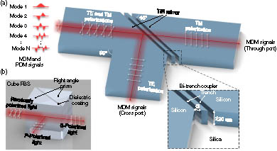
Fig. 1. (a) Schematic of the MTPBS based on multimode bus waveguides which support multiple mode channels. The modes are indistinguishable, while light can be distinguished by the polarization state. Dual-polarization MDM signals can be split into TE and TM polarizations. TE MDM signals are reflected at 90°, while TM MDM signals are transmitted straightly. The bi-trench coupler consists of a pair of total internal reflection (TIR) mirrors separated by fully etched trenches. (b) Cube PBS as an analogy of MTPBS. The cube PBS consists of a pair of right-angle prisms separated by a polarization-dependent dielectric coating on the hypotenuse of one of the prisms. P S
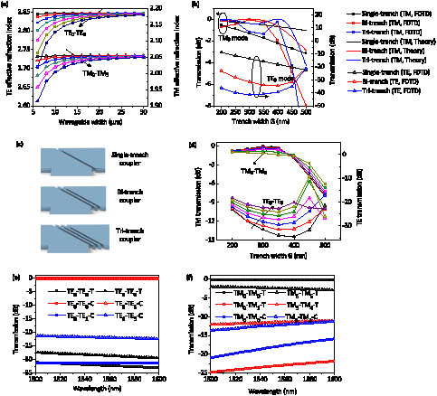
Fig. 2. (a) Calculated effective indices of eigenmodes in the waveguide with different widths. The square-curves and triangle-curves are for TE and TM polarizations, respectively. (b) The simulated power transmission efficiency at through port versus different trench widths for TE 0 TM 0 TE 0 − TE 6 TM 0 − TM 5 TE 0 TE 6 TM 0 TM 5 TM 0 − TM 1 − T TM 0 TM 1
Fig. 3. Simulated light propagation in the MTPBS for (a) TM 0 TM 5 TE 0 TE 6
Fig. 4. (a) Microscope view of the tested device with an input port and two output ports. Two tested devices with the same geometry but different mode multiplexers are needed for complete characterization. (b) Seven-TE-mode (de)multiplexer and (c) six-TM-mode (de)multiplexer are utilized to obtain single-polarization MDM signals individually. The adiabatic taper connects the TE/TM mode (de)multiplexer with the MTPBS. (d) Zoom-in view of MTPBS, where the TM grating is used to filter out the scattering light from TM polarization.
Fig. 5. (a) Schematic of i i mode conversion; two reversely tapered waveguides (access waveguide and bus waveguide) are placed closely to form a coupling region. The seven-TE-mode (de)multiplexer is composed of six cascaded ACs, which are used to excite TE 1 − TE 6 i i mode conversion. The six-TM-mode (de)multiplexer consists of five cascaded ADCs, which are used to excite TM 1 − TM 5
Fig. 6. Normalized spectra of the MTPBS when injecting TE 0 − TE 6 TE 1 − C TE 1
Fig. 7. Normalized spectra of the MTPBS when injecting TM 0 − TM 5 TM 1 − T TM 1


Set citation alerts for the article
Please enter your email address

© Copyright 2018-2021 | Chinese Laser Press. All Rights Reserved 沪ICP备15018463号-20