Author Affiliations
1The George Washington University, Department of Physics, Washington, DC, United States2King’s College London, Department of Physics and London Centre for Nanotechnology, London, United Kingdomshow less
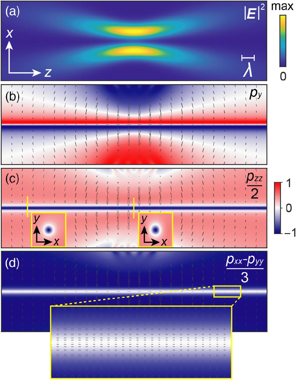
Fig. 1. Polarization parameters for a focused Laguerre–Gaussian vortex beam with l=1, linearly polarized along the direction and propagating along the axis. The beam waist is . (a) The intensity distribution of the beam in the () plane. (b–d) Colormaps of the (a) , (b) , and (d) polarization parameters with polarization ellipses overlaid on top, indicating the polarization state at each point in space. The polarization structure around the phase singularity is nondiffractive and invariant with respect to the beam waist. The inserts in (c) show the cross-sections at different positions. The insert in (d) shows the zoom near the beam centre.
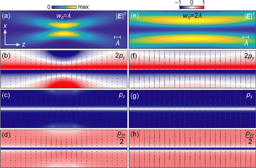
Fig. 2. Polarization parameters for a focused Laguerre–Gaussian vortex beam with l=1and (left-hand circularly polarized), propagating along the positive axis. The beam waist is (a–d) and (e–h) . (a) and (e) The intensity distribution of the beam in the () plane. (b–d) and (f–h) Colormaps of the (b,f) , (c,g) , and (d,h) polarization parameters with polarization ellipses overlaid on top, indicating the polarization state at each point in space. The polarization structure around the phase singularity is nondiffractive and invariant with respect to the beam waist.
Fig. 3. Cross sections of the linearly polarized vortex beams with depicted in Fig. 1 showing (a) and (b) at the focal plane and after propagating a distance of . The vertical dashed lines show the points at which and the corresponding field intensity for each cross-section plane.
Fig. 4. (a) The angular spectrum of a linearly polarized ( direction) vortex beam with l=1. The green line indicates the light line and the red dotted line indicates the inner limit of the cropped region dictated by the objective with . (b) The intensity distribution of the corresponding vortex beam with generated by integrating the field distribution in (a). The beam waist is . (c) Colormap of the polarization parameter with polarization ellipses overlaid on top, indicating the polarization state at each point in space. The nondiffractive behavior near the phase singularity is maintained and only peripheral fields are affected by the NA reduction. (d–f) The same quantities as in (a–c) but with part of the angular spectrum removed and astigmatism applied along direction.
Fig. 5. (a–d) The phase of in the focal plane of a nonparaxial l=3 vortex beam linearly polarized along direction with and (e–g) the polarization parameter in a plane (to avoid focal plane features) simulated for different finite numbers of constituent plane waves (indicated in the panels). The l=3 vortex splits in three l=1 vortices with an increased splitting for a decreased .
| Circular | Circular | Linear | Radial | Azimuthal | | | | | | | | | 1 | 0 | 0 | 0 | | | 0 | | | 0 | | | 0 | 0 | | 0 | | 0 | 0 | | | | | 0 | 0 | 0 | | | | | 0 | | 0 | 0 | | | 0 | 0 | 0 | 0 | | | 1 | | | 1 |
|
Table 1. Polarization parameters.