• Photonics Research
  • Vol. 5, Issue 2, 88 (2017)
Michael H. Frosz*, Paul Roth, Mehmet C. Günendi, and Philip St.J. Russell
Author Affiliations
  • Max Planck Institute for the Science of Light, Staudtstr. 2, D-91058 Erlangen, Germany
  • show less
    DOI: 10.1364/PRJ.5.000088 Cite this Article Set citation alerts
    Michael H. Frosz, Paul Roth, Mehmet C. Günendi, Philip St.J. Russell. Analytical formulation for the bend loss in single-ring hollow-core photonic crystal fibers[J]. Photonics Research, 2017, 5(2): 88 Copy Citation Text show less
    (a) Sketch of the geometry of a single-ring HC-PCF, showing the local coordinate system. The inner diameter of the six capillaries is d, and the core diameter (the minimum distance between two diametrically opposite capillaries) is D. (b) Index difference Δn0101 between LP01-like core and capillary modes, plotted against R/D for d/D=0.696 at four different values of λ/D.
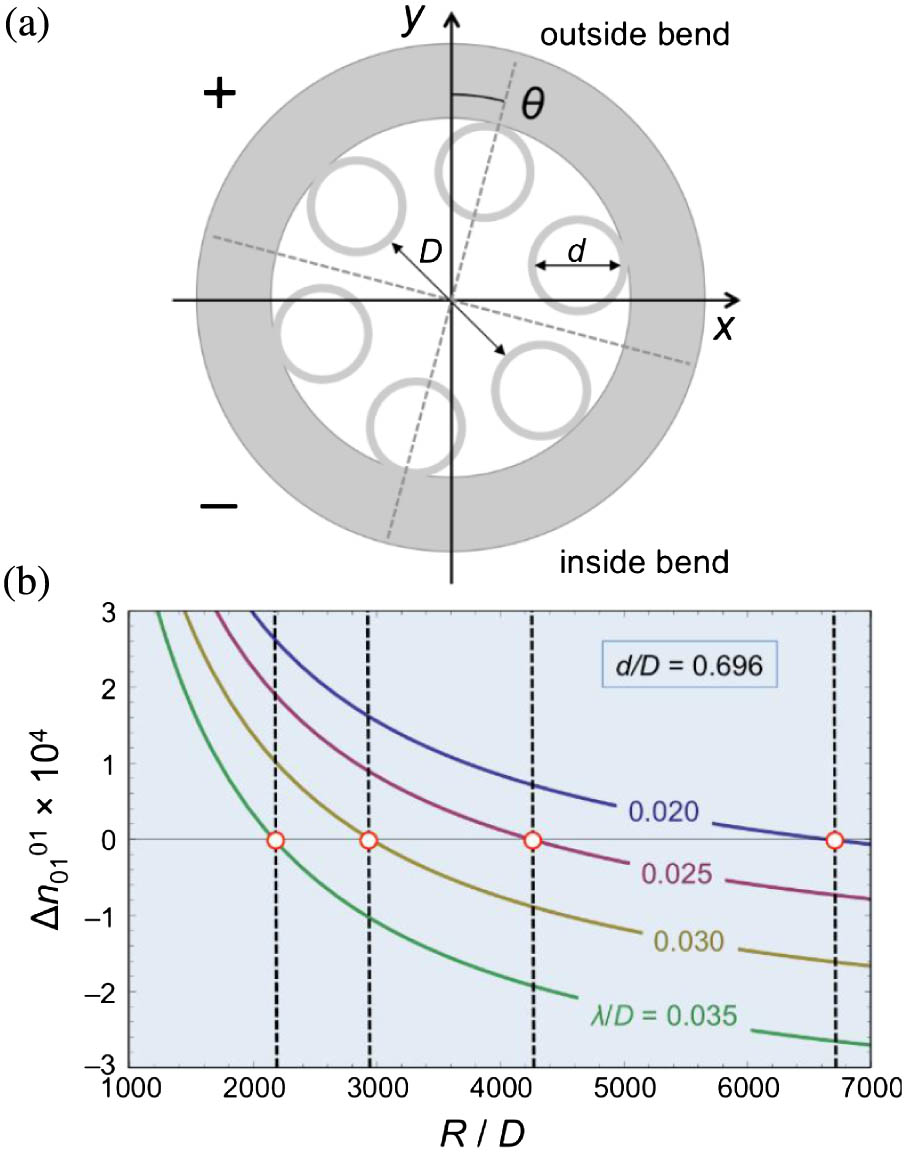
    Fig. 1. (a) Sketch of the geometry of a single-ring HC-PCF, showing the local coordinate system. The inner diameter of the six capillaries is d, and the core diameter (the minimum distance between two diametrically opposite capillaries) is D. (b) Index difference Δn0101 between LP01-like core and capillary modes, plotted against R/D for d/D=0.696 at four different values of λ/D.
    Numerically calculated axial Poynting vector distributions and loss α of a single-ring PCF with d=55 μm, D=79 μm, λ=2.8 μm and capillary wall thickness t=1.15 μm, for (a) bend radius slightly greater than Rcr01=17.2 cm, (b) close to Rcr01, and (c) and (d) close to the radius of curvature that phase-matches the LP01 core mode to capillaries placed at θ=±60°. The arrows indicate the polarization of the electric field.
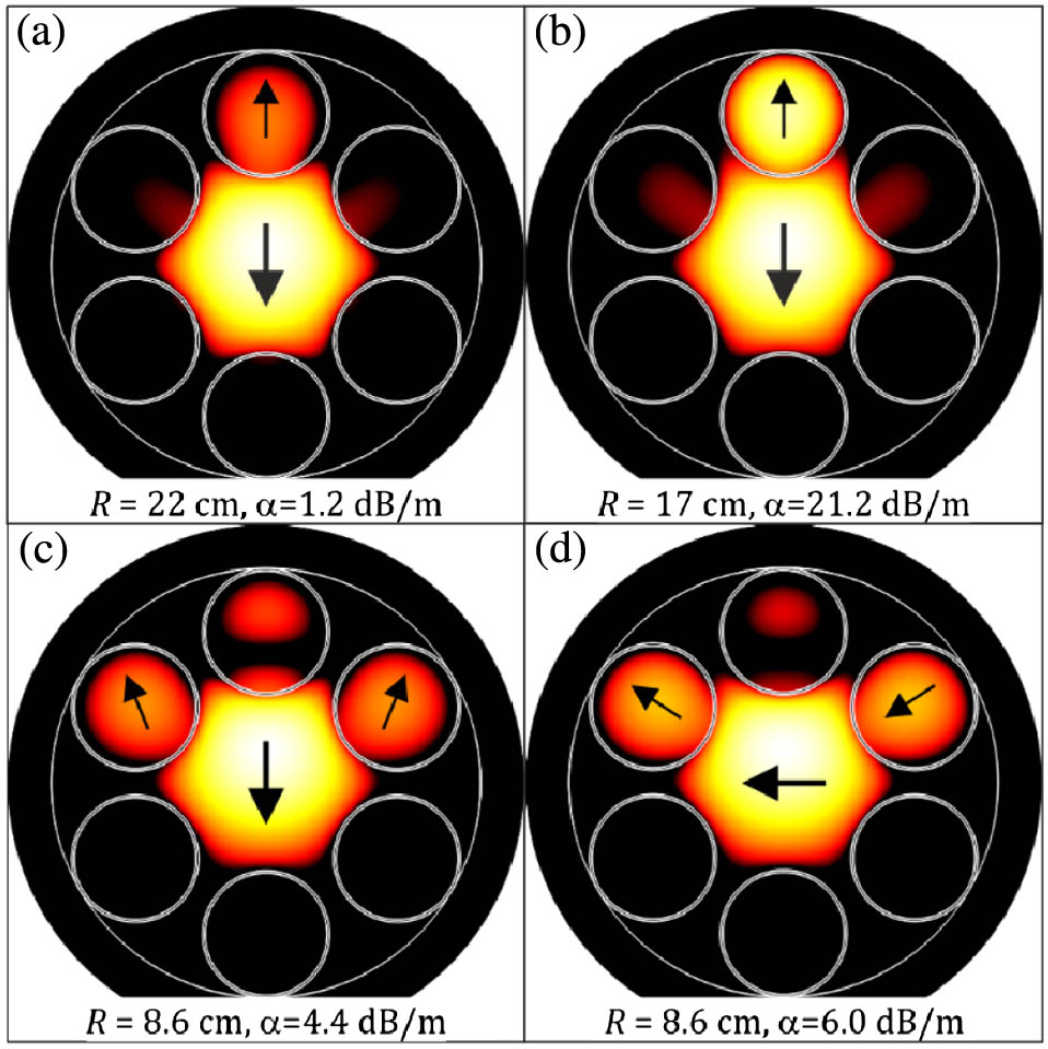
    Fig. 2. Numerically calculated axial Poynting vector distributions and loss α of a single-ring PCF with d=55  μm, D=79  μm, λ=2.8  μm and capillary wall thickness t=1.15  μm, for (a) bend radius slightly greater than Rcr01=17.2  cm, (b) close to Rcr01, and (c) and (d) close to the radius of curvature that phase-matches the LP01 core mode to capillaries placed at θ=±60°. The arrows indicate the polarization of the electric field.
    Numerically calculated bend loss for the fibers for θ=0°, plotted against normalized bend radius R/D. A:(d,D,λ)=(55,79,2.8) μm, i.e., d/D=0.70 and λ/D=0.035. B:(d,D,λ)=(22,36,1.2) μm, i.e., d/D=0.61, λ/D=0.033. The dashed vertical lines mark the corresponding analytical solutions for the critical bend radius using Eq. (4) with θ=0°. The dotted vertical line shows the bend radius for phase-matching to the capillaries at θ=±60°. In each case the loss is calculated for modes polarized normal to the bend, i.e., in the y direction in Fig. 1(a).
    Fig. 3. Numerically calculated bend loss for the fibers for θ=0°, plotted against normalized bend radius R/D. A:(d,D,λ)=(55,79,2.8)  μm, i.e., d/D=0.70 and λ/D=0.035. B:(d,D,λ)=(22,36,1.2)  μm, i.e., d/D=0.61, λ/D=0.033. The dashed vertical lines mark the corresponding analytical solutions for the critical bend radius using Eq. (4) with θ=0°. The dotted vertical line shows the bend radius for phase-matching to the capillaries at θ=±60°. In each case the loss is calculated for modes polarized normal to the bend, i.e., in the y direction in Fig. 1(a).
    Experimentally measured bend loss in two fibers with the same shape parameters as in Fig. (3). (a) d/D=0.70 and (b) d/D=0.61. The bend radii were changed in steps of 1.25 cm, and between these steps the colors are interpolated. The measured loss versus wavelength in (b) was smoothed with a moving average filter. The gray rectangle in (a) marks the region where the core mode phase-matches to a resonance in the walls of the capillaries, causing high attenuation. In each case, the white solid and dashed lines are solutions of Eq. (4) for θ=0° and θ=30°, respectively.
    Fig. 4. Experimentally measured bend loss in two fibers with the same shape parameters as in Fig. (3). (a) d/D=0.70 and (b) d/D=0.61. The bend radii were changed in steps of 1.25 cm, and between these steps the colors are interpolated. The measured loss versus wavelength in (b) was smoothed with a moving average filter. The gray rectangle in (a) marks the region where the core mode phase-matches to a resonance in the walls of the capillaries, causing high attenuation. In each case, the white solid and dashed lines are solutions of Eq. (4) for θ=0° and θ=30°, respectively.
    Michael H. Frosz, Paul Roth, Mehmet C. Günendi, Philip St.J. Russell. Analytical formulation for the bend loss in single-ring hollow-core photonic crystal fibers[J]. Photonics Research, 2017, 5(2): 88
    Download Citation