
Yanxing Ma, Jian Wu, Rongtao Su, Pengfei Ma, Pu Zhou, Xiaojun Xu, Yijun Zhao. Review of optical phased array techniques[J]. Infrared and Laser Engineering, 2020, 49(10): 20201042
- Infrared and Laser Engineering
- Vol. 49, Issue 10, 20201042 (2020)
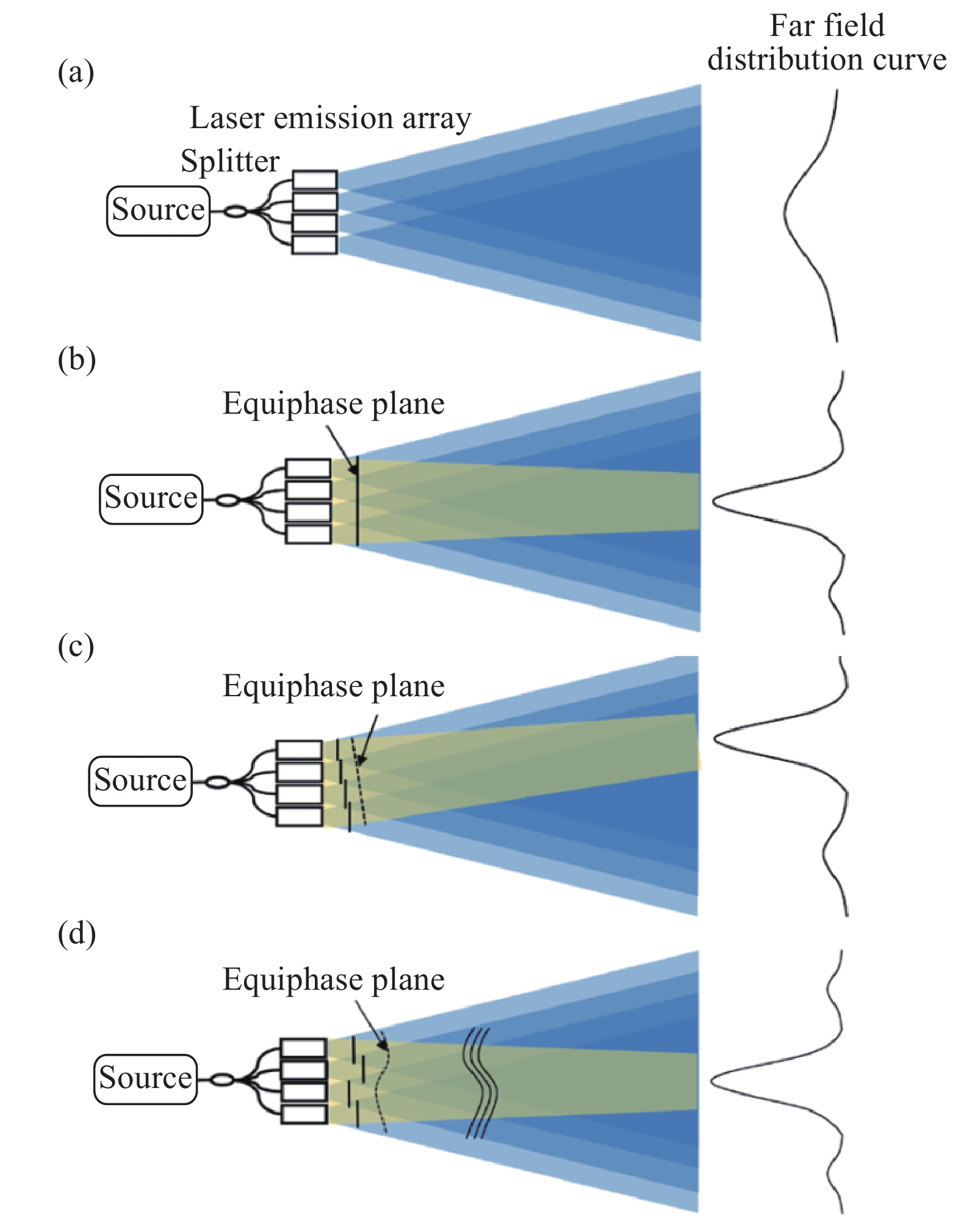
Fig. 1. Schematic of the optical phased array technology in beam launch

Fig. 2. Schematic of optical phased array technology in long-distance high-resolution imaging
Fig. 3. Schematic of COAT technology
Fig. 4. Schematic drawing of a two-element dithered COAT system
Fig. 5. Seven-element COAT experiment setup
Fig. 6. Experiment results of the 7 beams COAT
Fig. 7. Assembly of large-aperture transceiver telescope composed of adaptive phase-locked sub-apertures
Fig. 8. Schematic of phase locking and adaptive optical compensation control system in APPLE system
Fig. 9. Schematic and photo of 7 km target-in-the-loop coherent beam combination
Fig. 10. Experimental results of 7 km target-in-the-loop coherent beam combination
Fig. 11. Schematic and photo of MIT 64×64 photon phased array
Fig. 12. Experimental results of MIT 64×64 photon phased array
Fig. 13. Schematic of the 16-unit optical modulator array developed by IBM Laboratory based on the micromechanical structure in the display system in 1977
Fig. 14. Scanning electron microscope images of 8×8 HCG MEMS phased array device
Fig. 15. Photos of 160×160 MEMS phased array device prepared by the University of California research group in 2018
Fig. 16. High-power LCD and test site developed by Rockwell Scientific in 2006
Fig. 17. Schematic of 64-channel coherent beam combination of fiber lasers developed by Thales Research & Technology in 2011
Fig. 18. Schematic of 1.08 kW coherent beam combination of fiber lasers developed by NUDT in 2011
Fig. 19. Schematic of 4 kW coherent beam combination of fiber lasers developed by MIT in 2011
Fig. 20. Schematic and photo of 105.5 kW coherent beam combination of slab lasers developed by Northrop Grumman
Fig. 20. [in Chinese]
Fig. 21. Schematic of SPIDER
Fig. 22. Experimental results of SPIDER


Set citation alerts for the article
Please enter your email address

© Copyright 2018-2021 | Chinese Laser Press. All Rights Reserved 沪ICP备15018463号-20