• Photonics Research
  • Vol. 1, Issue 3, 124 (2013)
Ruixue Liu1、2、3, Yue Qi1、2、3, Xianliang Zheng1、2、3, Mingliang Xia3, and and Li Xuan1、*
Author Affiliations
  • 1State Key Laboratory of Applied Optics, Changchun Institute of Optics, Fine Mechanics and Physics, Chinese Academy of Sciences, Changchun, Jilin 130033, China
  • 2University of Chinese Academy of Sciences, Beijing 100039, China
  • 3Jiangsu Key Laboratory of Medical Optics, Suzhou Institute of Biomedical Engineering and Technology, Chinese Academy of Sciences, Suzhou, Jiangsu 215163, China
  • show less
    DOI: 10.1364/PRJ.1.000124 Cite this Article Set citation alerts
    Ruixue Liu, Yue Qi, Xianliang Zheng, Mingliang Xia, and Li Xuan. Flood-illuminated adaptive optics ophthalmoscope with a single curved relay mirror[J]. Photonics Research, 2013, 1(3): 124 Copy Citation Text show less
    Schematic of the single curved mirror AO ophthalmoscope. M1 is the curved mirror. L1 is an imaging lens. P is the focal point of the mirror. A polarization beam splitter (PBS) divides the light into two orthogonal polarization components, the S and P polarization components. The linearly polarized light whose direction is along the axis of the liquid crystal molecules will be used for correction and imaging. The light polarized orthogonally is received by the wavefront sensor for wavefront detection.
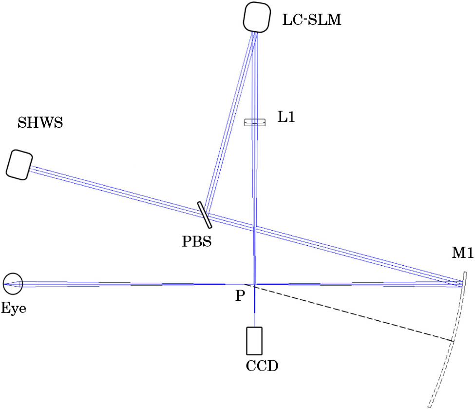
    Fig. 1. Schematic of the single curved mirror AO ophthalmoscope. M1 is the curved mirror. L1 is an imaging lens. P is the focal point of the mirror. A polarization beam splitter (PBS) divides the light into two orthogonal polarization components, the S and P polarization components. The linearly polarized light whose direction is along the axis of the liquid crystal molecules will be used for correction and imaging. The light polarized orthogonally is received by the wavefront sensor for wavefront detection.
    There are two sets of conjugate planes. One set is formed by the illumination source, the retina, and the CCD imaging planes. The other set is constituted by the pupil of the eye, the LC-SLM, and the wavefront sensor planes. (a) Commonly used 4F system. (b) Single-lens system. Both systems meet the conjugate relationships.
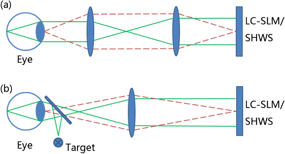
    Fig. 2. There are two sets of conjugate planes. One set is formed by the illumination source, the retina, and the CCD imaging planes. The other set is constituted by the pupil of the eye, the LC-SLM, and the wavefront sensor planes. (a) Commonly used 4F system. (b) Single-lens system. Both systems meet the conjugate relationships.
    Calculated wavefront of (a) the sensor and (b) the corrector by ZEMAX. The difference of the RMS values between them is 0.0007λ, which is so little that under the minimum detection size of the wavefront sensor (1/100λ).
    Fig. 3. Calculated wavefront of (a) the sensor and (b) the corrector by ZEMAX. The difference of the RMS values between them is 0.0007λ, which is so little that under the minimum detection size of the wavefront sensor (1/100λ).
    Schematic diagram of closed-loop optical configuration for measuring the response matrix. A point source is positioned at the imaging CCD and the light is propagated to the LC-SLM backward. The S polarization component is modulated and then it is turned into the P component by the half-wave plane (HWP). The P component can penetrate the PBS, and the unmodulated S component is abandoned. The quarter-wave plane (QWP) is carefully adjusted to make sure that the plane of polarization is rotated by 90° after the light traverses it twice. The P component becomes the S component on the way back and can be reflected to the wavefront sensor for measuring.
    Fig. 4. Schematic diagram of closed-loop optical configuration for measuring the response matrix. A point source is positioned at the imaging CCD and the light is propagated to the LC-SLM backward. The S polarization component is modulated and then it is turned into the P component by the half-wave plane (HWP). The P component can penetrate the PBS, and the unmodulated S component is abandoned. The quarter-wave plane (QWP) is carefully adjusted to make sure that the plane of polarization is rotated by 90° after the light traverses it twice. The P component becomes the S component on the way back and can be reflected to the wavefront sensor for measuring.
    Spot diagrams of the optical configuration on the imaging CCD plane, with (a) a spherical mirror, (b) a parabolic mirror, and (c) a hyperbolic mirror with conic constant −1.07. The FOV is 1° on the retina. The circle in every field is the Airy disk radius. The bar in the left image is 200 μm and in the other two is 100 μm.
    Fig. 5. Spot diagrams of the optical configuration on the imaging CCD plane, with (a) a spherical mirror, (b) a parabolic mirror, and (c) a hyperbolic mirror with conic constant 1.07. The FOV is 1° on the retina. The circle in every field is the Airy disk radius. The bar in the left image is 200 μm and in the other two is 100 μm.
    Wavefront of (a) the model eye and (b) the subject. The numbers on the bar represent the peak-to-valley (PV) wavefront error in wavelength (λ=808 nm).
    Fig. 6. Wavefront of (a) the model eye and (b) the subject. The numbers on the bar represent the peak-to-valley (PV) wavefront error in wavelength (λ=808nm).
    Three images are of the same location in the retina, about 3.5° from the foveal center. (a) Retina before the AO compensation. (b) Photoreceptors after the AO compensation. (c) Blood vessels after the AO compensation (Media 1).
    Fig. 7. Three images are of the same location in the retina, about 3.5° from the foveal center. (a) Retina before the AO compensation. (b) Photoreceptors after the AO compensation. (c) Blood vessels after the AO compensation (Media 1).
    Power spectra of the images with and without AO compensation are shown in (a) and (b), respectively.
    Fig. 8. Power spectra of the images with and without AO compensation are shown in (a) and (b), respectively.
    Image registration of different fields. There is a 70 μm displacement on the retina between the two fields.
    Fig. 9. Image registration of different fields. There is a 70 μm displacement on the retina between the two fields.
    Ruixue Liu, Yue Qi, Xianliang Zheng, Mingliang Xia, and Li Xuan. Flood-illuminated adaptive optics ophthalmoscope with a single curved relay mirror[J]. Photonics Research, 2013, 1(3): 124
    Download Citation