Abstract
For decreasing light loss and diminishing the aberrations of the optical system, an open-loop adaptive optics (AO) system for retinal imaging in vivo is introduced. Taking advantage of the ability of young human eyes to accommodate, there was only one single curved mirror to make the pupil of the eye conjugate with the wavefront corrector and the wavefront sensor. A liquid crystal spatial light modulator (LC-SLM) was adopted as the wavefront corrector because the LC-SLM can be made in a small size to match the sensor. To reduce a pair of lenses or focusing mirrors, the wavefront corrector and sensor are positioned in the noncommon path. The system adopts open-loop control and the high-precision LC-SLM guarantees the effectiveness of the AO system. The designed field of view is 1° on the retina (about 300 μm). The image quality was simulated with different mirror surface types, including circular, parabolic, and hyperbolic. A hyperbolic mirror with conic constant -1.07, which is close to -1, could best eliminate the aberrations. Theoretical analysis showed that the optical throughput of this system was at least 22.4% higher than that of a standard transmission AO system. In a practical experiment, a parabolic mirror was positioned in the optical path. Images of the cone photoreceptors and the capillary vessels were obtained successfully. This system simplifies the optical setup in comparison to the commonly used 4F systems while still guaranteeing the effectiveness of AO to correct the ocular aberrations.1. INTRODUCTION
The microscopic imaging of the retina plays an important role in vision science and in the early diagnosis of diseases [1–10]. The retina can be observed in vivo and noninvasively. However, ocular aberrations limit the resolution of retinal images. Adaptive optics (AO), which was proposed as a means of compensating for the wavefront distortion induced by atmospheric turbulence by the astronomer Babcock in 1953 [11], can also overcome blurs in eyes [12]. Incorporating AO into ophthalmic instruments supplies diffraction-limited retinal images. Photoreceptors, capillary vessels, nerve fiber bundles, and other tissues have been observed in vivo [12–15].
Since the introduction of AO technology to ophthalmic imaging, its components have been tailored to the properties of eyes. As civil medical equipment, AO retinal cameras require high availability and low cost. The wavefront corrector is the key and so far the most expensive component. Numerous types of correctors have been employed in AO systems for the eye [16–19]. Microelectromechanical systems [20] and liquid crystal spatial light modulators (LC-SLMs) [18,21–25], which are smaller and more cost effective, have been widely used instead of discrete actuator deformable mirrors [12]. The LC-SLM can be made in a small size, of which the aperture is comparable to the pupil of the eye. It has high spatial resolution and operates with low voltages. All these characteristics are propitious for miniaturizing the instrument. A limitation is that the LC-SLM can only modulate linearly polarized light in a certain direction. An open-loop AO system can utilize the rest of the light for measuring the wavefront [26].
Employing focusing mirrors rather than lenses is an effective way to reduce the number of optical elements and improve the energy efficiency. Due to the low reflectance of the retina and the maximum permissible exposure of the eye, AO systems operate in light-starved conditions. Thus, the systems would be susceptible to external disturbance, such as backreflection of lenses. To avoid it, focusing mirrors are employed in many AO applications, such as the AO scanning laser ophthalmoscope [15,20,27] and AO optical coherence tomography [28–31]. For a flood-illuminated AO system, it is not technically difficult to replace all lenses with aspheric mirrors. However, if too many mirrors are used, it is difficult to process and align. The mirrors have to be used off-axis and unwanted aberrations will be introduced inevitably. Every mirror should be carefully designed and adjusted to compensate for the coma generated by the previous reflection.
Sign up for Photonics Research TOC. Get the latest issue of Photonics Research delivered right to you!Sign up now
In this study, we introduce a reflective flood-illuminated AO system for retina imaging. The system was simplified as much as possible. Only one single curved mirror was used in the optical path to make the pupil of the eye conjugate with the LC-SLM and the Shack–Hartman wavefront sensor (SHWS). There were three fundamental properties of the designed system: the accommodation of the human eye, an open-loop control mode, and the same aperture of the LC-SLM and the wavefront sensor. A single parabolic mirror system was set up, and retinal images were observed successfully.
2. EXPERIMENTAL DESIGN AND METHODS
A schematic diagram of the open-loop AO system is shown in Fig. 1. The illumination part and the target are not demonstrated. Near-infrared light is preferred as the illumination source, which increases the reflectance from the retina and allows a larger permitted input level. A smaller number of frames can be collected and averaged for reducing the effect of the camera read noise. To keep the ability of accommodation in the proposed AO system, pupils are dilated without drugs but in a dark room. The eye is allowed to accommodate to a finite distance visual target. Similarly, the reflected light from the retina is allowed to focus on a finite distance plane. The image plane was adjusted to coincide with the focal plane of the following focusing mirror. The light became parallel light when arriving at the LC-SLM or wavefront sensor. Thus, the reference wavefront of the LC-SLM or wavefront sensor could be considered to be a plane wave. The structured target was positioned at 5 D before the eye. People with normal eyesight and myopia within 5 D could watch the target clearly. Spectacles can be used for others. The longitudinal chromatic aberration [32,33] and the steady-state accommodation error [34] introduce an axial shift of the reflected light from the retina. The actual focal point is approximately located at from 3 to 3.5 D.
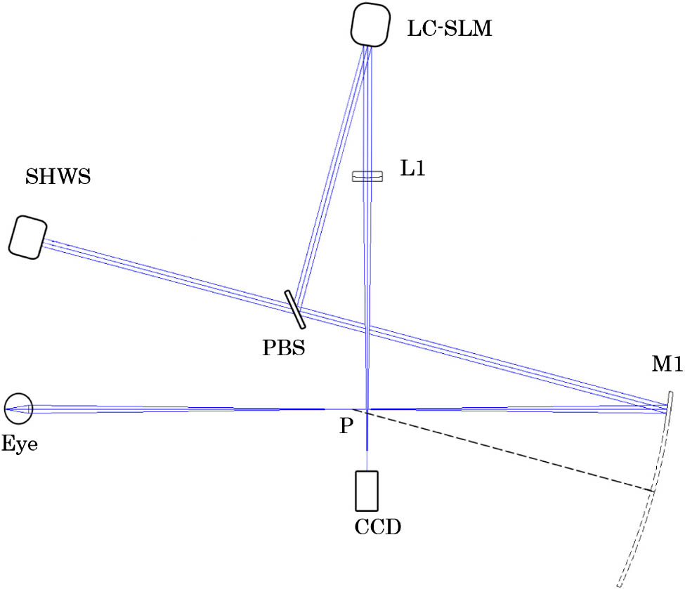
Figure 1.Schematic of the single curved mirror AO ophthalmoscope. M1 is the curved mirror. L1 is an imaging lens. P is the focal point of the mirror. A polarization beam splitter (PBS) divides the light into two orthogonal polarization components, the S and P polarization components. The linearly polarized light whose direction is along the axis of the liquid crystal molecules will be used for correction and imaging. The light polarized orthogonally is received by the wavefront sensor for wavefront detection.
In the AO system, it is important to keep track of two sets of conjugate planes. If the pupil position conjugates a different plane, the wavefront formed by off-axis points will be corrected with errors [35]. Ordinarily, the conjugated system is established based on a system, or in other words, a series of telescopes are employed to relay the light to the elements, which is shown in Fig. 2(a). In fact, the object–image relation can also be realized with one lens or one focusing mirror, which is shown in Fig. 2(b). The matching of the different aperture is controlled by the magnification.

Figure 2.There are two sets of conjugate planes. One set is formed by the illumination source, the retina, and the CCD imaging planes. The other set is constituted by the pupil of the eye, the LC-SLM, and the wavefront sensor planes. (a) Commonly used system. (b) Single-lens system. Both systems meet the conjugate relationships.
In a close-loop control AO system, the conjugate relationship between the wavefront corrector and the sensor could be achieved by a pair of lenses or focusing mirrors. However, in this open-loop system, the two elements are not included. Although the corrector and the sensor do not conjugate with each other, both of them conjugate with the pupil of the eye. For improving correction accuracy, the noncommon path aberrations should be calibrated. The wavefronts of the two branches are shown in Fig. 3 and were calculated by ZEMAX (Zemax Development Corporation, Bellevue, Washington, USA). The adopted LC-SLM ( pixels, aperture, XY series, Boulder Nonlinear Systems, CO, USA) has a phase modulation depth. A customized SHWS is employed in the AO system to measure the ocular aberration. The aperture of the lenslet array is 6.8 mm. The focal length and diameter of the subaperture are 6 mm and 340 μm. The CCD array (Du-897, Andor ixon) has pixels. The measurement accuracy can reach (root-mean-square [RMS]) in relative mode. In these conditions, the system aperture value is set as 6.5 mm, which is the designed diameter of the pupil. The wavefront corrector and the sensor are positioned just at twice the focal plane. To determine the response matrix, the wavefront sensor was required to measure the wavefront which had been modulated by the LC-SLM. However, for our noncommon path construction, the response matrix could not be measured directly. The open-loop configuration was transformed into a closed-loop system temporarily, which is shown in Fig. 4. In this way, the relationship between the wavefront corrector and the sensor can be accurately determined.
Figure 3.Calculated wavefront of (a) the sensor and (b) the corrector by ZEMAX. The difference of the RMS values between them is , which is so little that under the minimum detection size of the wavefront sensor ().
Figure 4.Schematic diagram of closed-loop optical configuration for measuring the response matrix. A point source is positioned at the imaging CCD and the light is propagated to the LC-SLM backward. The S polarization component is modulated and then it is turned into the P component by the half-wave plane (HWP). The P component can penetrate the PBS, and the unmodulated S component is abandoned. The quarter-wave plane (QWP) is carefully adjusted to make sure that the plane of polarization is rotated by 90° after the light traverses it twice. The P component becomes the S component on the way back and can be reflected to the wavefront sensor for measuring.
Astigmatism is the dominant aberration degrading image quality in the planes conjugate to the retina in a spherical reflective configuration. An effective method to significantly reduce this astigmatism is to orient a series of telescopes angled with respect to each other. However, there is only one curved mirror in our optical configuration. If a spherical mirror is employed, the astigmatism would not be eliminated unless a cylindrical lens is placed somewhere in the path. Using aspherical mirrors is another approach to reduce astigmatism, among which the most common is the parabolic mirror. The designed field of view (FOV) is 1° on the retina (about 300 μm). With the help of the software ZEMAX, the corresponding spot diagrams of the optical configuration with the spherical mirror and the aspherical mirrors are shown in Fig. 5. The wavefront RMS values for the different curved mirrors are , and , respectively, with . The spot diagrams of the spherical configuration correspond to the circle of least confusion for the astigmatism component, which is much larger than that of the aspherical mirrors. Remarkably, the aspherical mirrors reduced the wavefront RMS by more than a factor of 12. The hyperbolic mirror with conic constant could best eliminate the aberrations. Compared to the hyperbolic one, a parabolic mirror would introduce a slightly larger astigmatism but was easier to obtain. A parabolic mirror was adopted in the practice experiment. As shown in Fig. 1, the focus point P of the parabolic mirror M1 is also the image point of the retina. The focal length of M1 is 308.4 mm and the rotated angle is 15°.
Figure 5.Spot diagrams of the optical configuration on the imaging CCD plane, with (a) a spherical mirror, (b) a parabolic mirror, and (c) a hyperbolic mirror with conic constant . The FOV is 1° on the retina. The circle in every field is the Airy disk radius. The bar in the left image is 200 μm and in the other two is 100 μm.
In a standard transmission system, at least two pairs of lenses are employed to satisfy the conjugate relationship. The light intensity incident on the CCD could be calculated as where the coefficient of 0.5 means the beam splitter. is the light intensity at the position of the pupil, is the transmittance of the lens, and is the reflectivity of the LC-SLM. In the novel system, the light intensity incident can be expressed as where is the reflectivity of the curved mirror. We assume reasonably that the reflectivity is 99.7% and that the transmittance is 95%. Thus, according to Eqs. (1) and (2), the normalized intensity ratio between and is about 1.224 times. Consequently, the optical throughput of this system was at least 22.4% higher than that of a standard AO system.
A parabolic mirror was adopted in the practice experiment. For measuring the aberrations of the system itself, a model eye was detected first. The model eye consists of a short-focal-length lens and a white filter paper screen. The effective focal length of lens is 18 mm (), which is almost equal to the focal length of human eye. The contour profile of the lens is the mimetic pupil, and the size is 6.5 mm. Changing the distance between the lens and the paper screen can focus the light to the designed imaging plane. The main difference between the model and the real eye is that the former has little low-order wavefront distortions. The wavefront sensor measures the aberrations of both the eye and the optical elements of the ophthalmoscope. Thus, the astigmatism and the focus of the system can be easily observed.
A 24-year-old Chinese female was imaged using the single parabolic mirror system. The subject gave prior written consent in accordance with the Declaration of Helsinki. The degree of myopia of the subject was 2 D. She could recognize clearly the details of the 5 D target. After being in a dark room for 10 min, the pupils of the subject got wider than 6.5 mm, which was the size of the designed stop.
3. RESULTS AND DISCUSSION
Figure 6 shows the ocular aberrations of the model eye and the subject. The astigmatism of the model eye is small, which means the parabolic mirror does not introduce large distortion. In the image of the subject wavefront, defocus is not obvious because the accommodation plane of the eye is close to the focus point P of the parabolic mirror M1 in Fig. 1.
Figure 6.Wavefront of (a) the model eye and (b) the subject. The numbers on the bar represent the peak-to-valley (PV) wavefront error in wavelength ().
Figures 7(a) and 7(b) show the images of the photoreceptors without and with AO compensation, respectively. The imaging CCD can be moved to image different layers of the retina, and Fig 7(c) shows an image of capillary vessels at the same location. The image area was at about 3.5° from the fovea. The images with AO compensation show more details and have higher contrast.
Figure 7.Three images are of the same location in the retina, about 3.5° from the foveal center. (a) Retina before the AO compensation. (b) Photoreceptors after the AO compensation. (c) Blood vessels after the AO compensation (Media 1).
Continuous correction and imaging for the photoreceptors and blood vessels were performed. The results are shown in Media 1 (see Fig. 7), which was recorded at 20 frames per second (fps) for approximately 2.5 s but is displayed slowly at 8 fps to ensure that every frame is clear. Before the AO compensation shown in Media 1, the frames do not show any microscopic structure or significant contrast, although most of the defocus was corrected by the eye’s accommodation. With the lower and higher-order aberrations corrected after the AO compensation, the photoreceptors can be clearly observed. Media 1 also shows the process as the imaging plane is focused from the photoreceptor layer to the blood vessels. Among some adjacent frames, we can obviously observe the changes of bright spots in the blood vessels, which are caused by the blood flow.
The power spectra of Figs. 7(a) and 7(b) are shown in Figs. 8(a) and 8(b), respectively. The image before the AO compensation has little detail, so the energy is focused on the lower spatial frequency in Fig. 8(a). The range from 70 to is the spatial frequency range of the cone photoreceptors [36]. As shown in Fig. 8(b), the power spectrum of this range is significantly improved after AO compensation.
Figure 8.Power spectra of the images with and without AO compensation are shown in (a) and (b), respectively.
Figure 9 shows adjacent areas on the retina taken by moving the light source very slightly, which introduces a 70 μm displacement on the retina. The aim is to image the peripheral field. The designed FOV is 1°, which is less than the isoplanatic patch diameter. For avoiding the light spots on the wavefront sensor being too big to result in detection error, a shutter with a hole can be positioned in the illumination path [37]. Two light sources with different size of illumination area can also be adopted. In our experiment, devised only for testing and verifying the effectiveness of the reflective AO system, the illumination part was not well designed. A single laser diode was adopted for both detection and correction. Thus, the imaging area could not be too large and was limited to 0.4°. However, according to the simulation results mentioned above, the system can operate well for the whole FOV.
Figure 9.Image registration of different fields. There is a 70 μm displacement on the retina between the two fields.
The resolution of the ophthalmoscope was significantly improved by the single-mirror system. The diameter of the imaged cones is about 3 μm and that of the blood vessels is about 7 μm. However, the ring of the spatial frequency of the cone mosaic [36] is not obvious in Fig. 8(b). One reason may be that the shadow of a blood capillary is projected on the image of the photoreceptors in Fig. 7(b). The shadow affects the statistics of the spatial frequency of the photoreceptors. Another reason may be that some cones look mixed together in the obtained image. The higher resolution can be reached by dilating the pupils with mydriatics. Under this condition, the ciliary muscles of the eye are usually paralyzed and the ability to accommodate diminishes. However, trial lenses can be used to adjust the focus placement. Some measures may be taken to improve the contrast. Imaging with a shorter wavelength would contribute to viewing blood vessels [3]. Photoreceptors and other retinal features can be enhanced by imaging with depolarization lights [38].
4. CONCLUSION
A flood-illuminated AO ophthalmoscope with single-mirror relay optics has been presented. Taking advantage of the ability of young human eyes to accommodate, there was only one single curved mirror to make the pupil of the eye conjugate with the wavefront corrector and the wavefront sensor. An LC-SLM was adopted as the wavefront corrector, for that the LC-SLM can be made in a small size to matching the sensor. To reduce a pair of lenses or focusing mirrors, the wavefront corrector and sensor are positioned in the noncommon path. The system adopts open-loop control, and the high-precision LC-SLM guarantees the effectiveness of the AO system. The optical throughput can reach about 22.4% higher than that of a conventional transmission LC-SLM AO system. The optical performance of three mirror surface types was simulated, and the more common parabolic mirror was adopted in the experiment. The astigmatism of the system was acceptable both for the software simulation and the practical experiment. A subject was imaged using the single parabolic mirror system. Images of cone photoreceptors and capillary vessels were obtained successfully. Reforming the current illumination part of the system would allow us to image the whole 1° designed FOV in the future. This system simplifies the optical setup while still guaranteeing the effectiveness of AO to correct the ocular aberrations.
References
[1] A. Roorda, D. R. Williams. The arrangement of the three cone classes in the living human eye. Nature, 397, 520-522(1999).
[2] J. I. Wolfing, M. Chung, J. Carroll, A. Roorda, D. R. Williams. High-resolution retinal imaging of cone-rod dystrophy. Ophthalmology, 113, 1014(2006).
[3] J. A. Martin, A. Roorda. Pulsatility of parafoveal capillary leukocytes. Exp. Eye Res., 88, 356-360(2009).
[4] J. M. Gelfand, J. L. Duncan, C. A. Racine, L. A. Gillum, C. T. Chin, Y. Zhang, Q. Zhang, L. J. Wong, A. Roorda, A. J. Green. Heterogeneous patterns of tissue injury in NARP syndrome. J. Neurol., 258, 440-448(2011).
[5] J. L. Duncan, K. Ratnam, D. G. Birch, S. M. Sundquist, A. S. Lucero, Y. Zhang, M. Meltzer, N. Smaoui, A. Roorda. Abnormal cone structure in foveal schisis cavities in X-linked retinoschisis from mutations in exon 6 of the RS1 gene. Investig. Ophthalmol. Vis. Sci., 52, 9614-9623(2011).
[6] R. S. Jonnal, O. P. Kocaoglu, Q. Wang, S. Lee, D. T. Miller. Phase-sensitive imaging of the outer retina using optical coherence tomography and adaptive optics. Biomed. Opt. Express, 3, 104-124(2012).
[7] J. L. Duncan, A. Roorda, M. Navani, S. Vishweswaraiah, R. Syed, S. Soudry, K. Ratnam, H. V. Gudiseva, P. Lee, T. Gaasterland, R. Ayyagari. Identification of a novel mutation in the CDHR1 Gene in a family with recessive retinal degeneration. Arch. Ophthalmol., 130, 1301-1308(2012).
[8] C. Correia, J. P. Veran, G. Herriot. Advanced vibration suppression algorithms in adaptive optics systems. J. Opt. Soc. Am. A, 29, 185-194(2012).
[9] R. Legras, Y. Benard, N. Lopez-Gil. Effect of coma and spherical aberration on depth-of-focus measured using adaptive optics and computationally blurred images. J. Cataract. Refract. Surg., 38, 458-469(2012).
[10] H. J. Hofer, J. Blaschke, J. Patolia, D. E. Koenig. Fixation light hue bias revisited: implications for using adaptive optics to study color vision. Vis. Res., 56, 49-56(2012).
[11] H. W. Babcock. The possibility of compensating astronomical seeing. Publ. Astron. Soc. Pac., 65, 229-236(1953).
[12] J. Liang, D. R. Williams, D. T. Miller. Supernormal vision and high-resolution retinal imaging through adaptive optics. J. Opt. Soc. Am. A, 14, 2884-2892(1997).
[13] A. Dubra, Y. Sulai, J. L. Norris, R. F. Cooper, A. M. Dubis, D. R. Williams, J. Carroll. Noninvasive imaging of the human rod photoreceptor mosaic using a confocal adaptive optics scanning ophthalmoscope. Biomed. Opt. Express, 2, 1864-1876(2011).
[14] N. Doble, S. S. Choi, J. L. Codona, J. Christou, J. M. Enoch, D. R. Williams. In vivo imaging of the human rod photoreceptor mosaic. Opt. Lett., 36, 31-33(2011).
[15] A. Roorda, F. Romero-Borja, W. Donnelly, H. Queener, T. Hebert, M. Campbell. Adaptive optics scanning laser ophthalmoscopy. Opt. Express, 10, 405-412(2002).
[16] D. Miller, L. Thibos, X. Hong. Requirements for segmented correctors for diffraction-limited performance in the human eye. Opt. Express, 13, 275-289(2005).
[17] N. Doble, D. T. Miller, G. Yoon, D. R. Williams. Requirements for discrete actuator and segmented wavefront correctors for aberration compensation in two large populations of human eyes. Appl. Opt., 46, 4501-4514(2007).
[18] G. D. Love, J. V. Major, A. Purvis. Liquid-crystal prisms for tip-tilt adaptive optics. Opt. Lett., 19, 1170-1172(1994).
[19] G. D. Love, N. Andrews, P. Birch, D. Buscher, P. Doel, C. Dunlop, J. Major, R. Myers, A. Purvis, R. Sharples, A. Vick, A. Zadrozny, S. R. Restaino, A. Glindemann. Binary adaptive optics: atmospheric wave-front correction with a half-wave phase shifter. Appl. Opt., 34, 6058-6066(1995).
[20] Y. Zhang, S. Poonja, A. Roorda. MEMS-based adaptive optics scanning laser ophthalmoscopy. Opt. Lett., 31, 1268-1270(2006).
[21] L. N. Thibos, A. Bradley. Use of liquid-crystal adaptive-optics to alter the refractive state of the eye. Optom. Vis. Sci., 74, 581-587(1997).
[22] Q. Mu, Z. Cao, D. Li, L. Hu, L. Xuan. Liquid Crystal based adaptive optics system to compensate both low and high order aberrations in a model eye. Opt. Express, 15, 1946-1953(2007).
[23] C. Li, M. Xia, Q. Mu, B. Jiang, L. Xuan, Z. Cao. High-precision open-loop adaptive optics system based on LC-SLM. Opt. Express, 17, 10774-10781(2009).
[24] P. Prieto, E. Fernandez, S. Manzanera, P. Artal. Adaptive optics with a programmable phase modulator: applications in the human eye. Opt. Express, 12, 4059-4071(2004).
[25] Q. Mu, Z. Cao, L. Hu, D. Li, L. Xuan. An adaptive optics imaging system based on a high-resolution liquid crystal on silicon device. Opt. Express, 14, 8013-8018(2006).
[26] C. Li, M. Xia, D. Li, Q. Mu, L. Xuan. High-resolution retinal imaging through open-loop adaptive optics. J. Biomed. Opt., 15, 046009(2010).
[27] K. Venkateswaran, A. Roorda, F. Romero-Borja. Theoretical modeling and evaluation of the axial resolution of the adaptive optics scanning laser ophthalmoscope. J. Biomed. Opt., 9, 132-138(2004).
[28] B. Hermann, E. J. Fernandez, A. Unterhuber, H. Sattmann, A. F. Fercher, W. Drexler, P. M. Prieto, P. Artal. Adaptive-optics ultrahigh-resolution optical coherence tomography. Opt. Lett., 29, 2142-2144(2004).
[29] Y. Zhang, J. Rha, R. Jonnal, D. Miller. Adaptive optics parallel spectral domain optical coherence tomography for imaging the living retina. Opt. Express, 13, 4792-4811(2005).
[30] E. J. Fernandez, B. Povazay, B. Hermann, A. Unterhuber, H. Sattmann, P. M. Prieto, R. Leitgeb, P. Ahnelt, P. Artal, W. Drexler. Three-dimensional adaptive optics ultrahigh-resolution optical coherence tomography using a liquid crystal spatial light modulator. Vis. Res., 45, 3432-3444(2005).
[31] R. J. Zawadzki, S. M. Jones, S. S. Olivier, M. Zhao, B. A. Bower, J. A. Izatt, S. Choi, S. Laut, J. S. Werner. Adaptive-optics optical coherence tomography for high-resolution and high-speed 3D retinal in vivo imaging. Opt. Express, 13, 8532-8546(2005).
[32] D. A. Atchison, G. Smith. Chromatic dispersions of the ocular media of human eyes. J. Opt. Soc. Am. A, 22, 29-37(2005).
[33] K. Grieve, P. Tiruveedhula, Y. Zhang, A. Roorda. Multi-wavelength imaging with the adaptive optics scanning laser ophthalmoscope. Opt. Express, 14, 12230-12242(2006).
[34] B. Wang, K. J. Ciuffreda. Depth-of-focus of the human eye: theory and clinical implications. Surv. Ophthalmol., 51, 75-85(2006).
[35] J. Porter, J. E. Lin, K. Thorn, A. Awwal. Adaptive Optics for Vision Science, 156-157(2006).
[36] J. I. Yellott. Spectral analysis of spatial sampling by photoreceptors: topological disorder prevents aliasing. Vis. Res., 22, 1205-1210(1982).
[37] N. Kong, C. Li, M. Xia, D. Li, Y. Qi, L. Xuan. Optimization of the open-loop liquid crystal adaptive optics retinal imaging system. J. Biomed. Opt., 17, 026001(2012).
[38] H. Song, Y. Zhao, X. Qi, Y. T. Chui, S. A. Burns. Stokes vector analysis of adaptive optics images of the retina. Opt. Lett., 33, 137-139(2008).


