Abstract
Hybrid square/rhombus-rectangular lasers (HSRRLs) consisting of a Fabry–Perot (FP) cavity and a square/rhombus microcavity (SRM) are proposed and demonstrated for realizing single-mode lasing with a wide wavelength tuning range. The SRM is a deformed square microcavity with a vertex extended to the FP cavity to control the coupled mode field pattern in the FP cavity. Single-mode operation with a side-mode suppression ratio (SMSR) over 45.3 dB is realized, and a wide wavelength tuning range of 21 nm with SMSR is further demonstrated by adjusting the injection currents of the SRM and the FP cavity simultaneously. Furthermore, a 3-dB modulation bandwidth of 14.1 GHz and an open-eye diagram at 35 Gb/s are demonstrated for the HSRRL.1. INTRODUCTION
Wavelength tunable semiconductor lasers are in great demand for high-speed, large-capacity optical communication and interconnection [1–3]. Distributed feedback (DFB) laser arrays [4,5], distributed Bragg reflector (DBR) lasers [6], sampled grating DBR lasers [7,8], superstructure grating DBR lasers [9,10], and digital supermode DBR lasers [11] were investigated for realizing wavelength tuning semiconductor lasers. In addition, coupled cavity lasers based on the Vernier effect, such as etched groove and cleaved coupled-cavity lasers [12], Y-branch lasers [13], V-coupled cavity lasers [14,15], and coupled-ring lasers [16,17] were applied for single-mode and tunable semiconductor lasers. Recently, etched-slot based lasers [18] and multichannel interference lasers [19,20] were reported to achieve a good performance in wavelength tuning range and side-mode suppression ratios (SMSRs). Furthermore, a hybrid square-rectangular laser (HSRL) as a coupled cavity consisting of a square microcavity and a Fabry–Perot (FP) cavity has been demonstrated for mode factor control and single-mode operation [21–23]. All-optical flip-flop is realized based on the optical bistability caused by saturable absorption and mode competition [24,25], and all-optical switch and logic gates of NOT and NOR are demonstrated by using HSRLs [26].
However, a coupled-mode field pattern in the FP cavity of the HSRL is a mixture of fundamental transverse mode and symmetric high-order modes, which may reduce the coupling efficiency into a single-mode fiber (SMF). For improving the performance of this kind of coupled cavity, it is necessary to optimize the mode field pattern and increase the proportion of the fundamental transverse mode in the FP cavity. In this paper, we report a hybrid square/rhombus-rectangular laser (HSRRL) composed of a square/rhombus microcavity (SRM) and an FP cavity for improving the mode field pattern in the FP cavity. The mode field distributions inside the hybrid cavity and the far-field patterns are numerically simulated for the HSRRL with an optimized SRM, which shows a near fundamental-transverse-mode distribution in the FP cavity and improved far-field patterns. The SRMs work as a wavelength selective reflector for the FP cavity, with the effective reflectivity related to the mode in the SRM. The results indicate that a properly deformed SRM has more stable mode selection properties than that with a square microcavity. HSRRLs with different sizes are fabricated, and single-mode operation is realized with an SMSR over 45.3 dB. Furthermore, the wavelength tuning is achieved by varying injection currents into the SRM and FP cavity. Finally, the direct modulation characteristics are investigated for an HSRRL, and an open-eye diagram at 35 Gb/s is demonstrated.
2. DEVICE STRUCTURE AND SIMULATION
As shown in Fig. 1(a), an HSRRL consists of an FP cavity with a width , a length , and an SRM with a side length and a deformation amplitude . A two-dimensional finite-difference time-domain (FDTD) method is used to investigate the reflection behaviors of the SRM as an equivalent reflector. The FDTD simulation region covers the entire SRM and part of the FP cavity, in which the end of the waveguide is embedded into the perfectly matched layer (PML) to ensure no backreflection from the waveguide facet. The practical devices are surrounded by bisbenzocyclobutene (BCB), and the effective refractive indices of the HSRRL cavity and the BCB medium are assumed to be 3.2 and 1.54, respectively. A wide-band exciting source with a Gaussian profile, is set in the FP cavity 12 μm away from the center of the SRM with , , and . The reflectivity is defined as the ratio of reflected energy to incident energy and is obtained from the FDTD time domain output and the Padé approximation method based on Baker’s algorithm [27]. The intensity detector is set at the midpoint of the FP cavity 15 μm away from the center of the SRM.
Sign up for Photonics Research TOC. Get the latest issue of Photonics Research delivered right to you!Sign up now
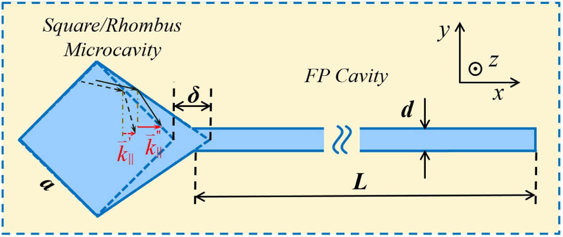
Figure 1.Schematic diagram of the coupled-cavity laser composed of an FP cavity and a square/rhombus microcavity as a deformed square microcavity with a vertex extending a distance of , and the wave vectors for the mode light rays reflected from the sides of the SRM and the square microcavity.
The reflectivity spectra of the transverse-electric (TE) modes for the SRMs are shown in Figs. 2(a) and 2(b), where the black solid and red dotted lines correspond to reflectivity at the gain of 0 and in the SRM, respectively. For the SRM with and , two maximums, and , appear at 1541.5 and 1594.8 nm, with an interval of 53.3 nm, as shown in Fig. 2(a), which is equal to 2 times the free spectral range of the four-bounced whispering-gallery modes in the SRM with . The reflectivities of the modes and are higher than those of other modes. Compared with the hybrid square-rectangle laser in Ref. [22], the reflectivity peaks of modes and are much wider, and the peak values are insensitive to the gain at low gain level, because of the low-mode factors for the SRM. Figure 2(b) shows the reflection characteristics for an SRM with and . Selective reflection is also observed with the maximums and at 1530.5 and 1565.2 nm, with an interval of 34.7 nm. The reflectivity changes of the SRM with are more obvious than that of the SRM with under the same gain conditions, owing to higher-mode factors in the larger cavities. Some peaks have the reflectivity larger than unity without gain, as shown in Fig. 2(b), because the reflected fields in the waveguide contain not only the fundamental waveguide mode but also symmetric higher-order modes, which will result in overestimation of the reflectivity under the simplified calculated method [22]. The optical reflection from a waveguide directly connected to a high- silicon microdisk was applied in monitoring nanoparticles and ambient changes [28] where the waveguide was a single-mode waveguide.

Figure 2.Simulated reflectivity spectra at different gain levels obtained by FDTD simulation for an SRM connected to a vertex waveguide, with (a) the side length , the deformation amplitude , and waveguide width and (b) , , and , respectively. (c) Reflectivity for the modes , , , and for the mode versus the deformation amplitude for an HSRRL with , , and .
Taking into account the reflectivity of the SRM and the confined mode in the FP cavity, we select the deformation and the size of the HSRRL. The proportion of the fundamental transverse mode in the FP cavity is defined by where is the simulated -direction magnetic field in the FP cavity of an HSRRL, and is the fundamental transverse mode in the slab waveguide of the corresponding FP cavity. The reflectivity for the modes , , , and for the mode versus are plotted as solid lines and a dashed line in Fig. 2(c) for an HSRRL with , , and . The deformation is chosen with the near highest values of the reflectivity and for the mode .
Mode field patterns of the -direction magnetic field are simulated for an HSRRL with , , , and and plotted in Fig. 3(a) for TE mode at 1541.5 nm, and detailed distributions in the SRM and the FP cavity are illustrated in Figs. 3(b) and 3(c), respectively. Moreover, the far-field distributions are calculated from the complex near-field mode distributions [29] with a far-field angle of about 28°, as shown in Fig. 3(d). The deformation induces an additional wave vector along the coupled waveguide axis for the mode light rays reflected from the two deviated sides of the SRM, which forces the transfer of the mode field pattern inside the SRM from the higher-order transverse mode to the fundamental mode in the FP cavity, as shown in Fig. 3(b), because of the reduction of the -direction propagation constant with the increase of the -direction propagation constant.
Figure 3.Mode intensity profiles of in the (a) HSRRL, (b) SRM, and (c) FP cavity, and (d) simulated far-field intensity at 1541.5 nm.
The numerical result of is 0.906 for the hybrid mode in Fig. 3. Owing to the mode field pattern in the FP cavity, there is a mixture of the fundamental transverse mode and symmetric high-order modes; the mode field patterns are different in the FP cavity with different FP cavity lengths . Mode field patterns near the output facet are shown in Figs. 4(a)–4(c) for coupled cavities with , 290, and 310 μm, where can stay above 90% for the HSRRLs, as shown in Fig. 4. The simulated far-field intensity profiles out of the output facet of the HSRRLs are also shown in Figs. 4(a)–4(c), where the integral is along an arbitrary right perimeter of the external region surrounding the coupled cavity. Compared with the far-field patterns for HSRLs with the same FP cavity length, as shown in Figs. 4(d)–4(f), we can optimize the mode field pattern and enhance the proportion of the fundamental transverse mode in the FP cavity, which would make the coupled mode stabler.
Figure 4.Simulated far-field intensity profiles and mode intensity profiles of of high- modes in the HSRRLs with , , , and 280 μm, (b) 290 μm, and (c) 310 μm, and the HSRL with , , and 280 μm, (e) 290 μm, and (f) 310 μm. The proportions of the fundamental transverse mode in the FP cavity are given for the coupled modes.
3. EXPERIMENTAL RESULTS AND DISCUSSION
The HSRRLs are fabricated by standard contact photolithography and inductively coupled plasma (ICP) techniques, as in Ref. [21]. After deep etching by ICP, the coupled cavity is confined by a 200-nm layer and a BCB layer for planarization. A 250-nm- layer is grown by plasma-enhanced chemical vapor deposition (PECVD) and utilized as the hard mask to form the electrical isolation trench between the SRM cavity and FP cavity. The lasers are cleaved with the FP cavity length about 300 μm and mounted P-side up on an AlN submount for controlling the temperature. Figure 5 shows a microscopic image of an HSRRL with , , and , after the deposition of two patterned p-electrodes and an n-type backside electrode. Two patterned p-type electrodes are used for current injection into the hybrid square/rhombus and FP cavities separately. Based on the simulation results and technology experiences, the side length of the square microcavity was chosen at 10–20 μm to avoid a large vertical radiation loss for a smaller microcavity and multiple-mode operation for a larger microcavity. The width of the FP cavity was chosen at 1.5–3 μm, much larger than the single-mode waveguide, which is limited by the contacting photolithography and the deep dry etching.
Figure 5.Microscopic image of an HSRRL with patterned p-electrodes for current injection into the SRM and FP cavities separately.
Output powers coupled into an SMF versus at , 1, 5, and 30 mA are measured and plotted in Fig. 6(a) for an HSRRL with , , and . The threshold current is about 15 mA under different , which is in agreement with the numerical results in Fig. 2(a), where the reflectivity is little affected by the gain at . The maximum power is about 2.6 mW, with nearly the same output power at , 1, and 5 mA. The output power is even lower at owing to the thermal cross talk between two cavities. For an HSRRL with , , and , the output powers collected by an SMF versus are measured and plotted in Fig. 6(b) at , 10, and 25 mA. The threshold current reduced from 17 to 13 mA when was increased from 0 to 25 mA, as shown in Fig. 6(b), due to the improvement of equivalent reflectivity, as shown in Fig. 2(b). The maximum output power collected by the SMF is 6.14 mW. The slope efficiencies are estimated to be about 0.06 and 0.13 W/A before the saturation for the HSRRLs with and 15 μm, respectively.
Figure 6.Output powers coupled into an SMF versus as is fixed at different currents for HSRRLs at , , with (a) , and (b) , .
Then, the lasing spectra are measured for the HSRRLs under different injection currents. As shown in the inset of Fig. 7(a), the laser operates in stable single mode at 1574.27 nm with an SMSR of 45.3 dB, as and for the HSRRL with , , , and , which verifies the excellent mode selection capacity for HSRRLs. Lasing spectra versus are shown in Fig. 7(a) at . The lasing mode wavelength redshifts from 1567.7 to 1589.8 nm as increases from 8 to 80 mA. The lasing wavelengths and corresponding SMSRs are plotted in Fig. 7(c), and the interval between every two lasing modes is about 1.4 nm. Similarly, the lasing spectra, lasing mode wavelengths, and SMSRs versus are plotted in Figs. 7(b) and 7(d) at . The wavelength can shift over 2.5 nm with high SMSR by changing . So, the lasing mode wavelength can be continuously tuned in a wide range by varying and adjusting slightly. The shift of the wavelength is mainly due to the change in refractive index caused by the thermal effect when changing the injection currents of the SRM and the FP cavity. Continuous wavelength tuning ranges over 21 and 29 nm are demonstrated, as shown in Figs. 8(a) and 8(b), for the HSRRLs by adjusting the and simultaneously. Their corresponding SMSRs and peak powers obtained from the spectra are plotted in Figs. 8(c) and 8(d). The SMSR is larger than 40 dB over 18 nm for the HSRRL with in Fig. 8(c), because of the higher reflectivity and better heat conducting of the SRM. In Fig. 8(d), most SMSRs are larger than 30 dB in the tuning range. Increasing the mode factor and enhancing the mode reflectivity by coating the SRM with a metal layer can improve the performance of the HSRRLs, as in Ref. [30]. For the HSRL in Ref. [21], the lasing mode is easy to jump to another coupled mode of different microcavity mode with the injection current due to the redshift of gain spectrum, because the reflectivity of the square microcavity is sensitive to the mode gain. The deformed SRM has more stable mode selection properties because the reflectivity of the SRM is little affected by the practical gain value, and a large wavelength tunable range is achieved for the HSRRL. Furthermore, the far-field profiles are measured with the full width at half-maximum of 44° and 43° in the in-plane and out-of-plane directions for an HSRRL, which are similar to the HSRL in Ref. [21]. In fact, high-order transverse modes in the HSRL are even-order transverse modes, which mainly affect the detailed pattern instead of the width of the far-field pattern, as shown in Fig. 4. The near-symmetric output pattern leads to a high coupling efficiency to an SMF.
Figure 7.Lasing characteristics with the variations of and for the HSRRL with , , , and . Lasing spectra (a) versus at and (b) versus at . Dominant lasing mode wavelengths and corresponding SMSRs (c) versus at and (d) versus at , respectively.
Figure 8.Superimposed lasing spectra for HSRRLs at , with (a) , and (b) , , and their corresponding SMSRs and peak powers at (c) and (d) .
Finally, high-speed experiments at room temperature are conducted for the HSRRL with , , , and by mounting the HSRRL onto an AlN submount. Considering the series resistor of the lasers, we chose a resistor of 40 Ω on the AlN submount to reduce the electrical return loss. The modulation signal together with the DC injection current is fed into the FP cavity using a 40-GHz bias-tee and a 40-GHz radio-frequency probe. The output power is coupled into a tapered SMF, and then converted into electrical signals through a 28-GHz high-speed photodetector. The small signal modulation responses measured by a 40-GHz-bandwidth network analyzer are plotted in Fig. 9(a), where 3-dB bandwidth increases from 9.5 to 14.1 GHz, and the corresponding resonance peak decreases from 4.46 to 0.94 dB as increases from 30 to 70 mA. The response curves are fitted by the modulation transfer function [31] as solid lines in Fig. 9(a). The fitted resonance frequency and 3-dB bandwidth are plotted as functions of in Fig. 9(b). Based on this, we get the factor [32] and modulation current efficiency factor of 2.04 and . The saturation of the resonance frequency and 3-dB bandwidths is mainly caused by the thermal effect.
Figure 9.Small single modulation responses of an HSRRL with , , , and . (a) Small signal modulation responses at , 40, and 70 mA; (b) fitted resonance frequency and 3-dB bandwidth vary by the square root of the injection current of the FP cavity and as a function of at .
Utilizing a 64 Gb/s pulse-pattern generator to supply the modulation current, we perform large-signal modulation measurement using a high-speed photodetector with 70-GHz bandwidth and a 90-GHz digital sampling oscilloscope. Figures 10(a) and 10(b) show the 25-Gb/s and 35-Gb/s eye diagrams for back-to-back (BTB) configuration with a nonreturn-to-zero (NRZ) pseudo-random binary sequence (PRBS) of input into the FP cavity. The wavelength of the laser was 1571 nm. The bias current was 68 mA for the FP cavity, and the modulation voltage was 1.5 V peak-to-peak.
Figure 10.(a) 25-Gb/s and (b) 35-Gb/s eye diagrams for HSRRL with , , , and at and .
4. CONCLUSIONS
In conclusion, we have proposed and demonstrated a hybrid square/rhombus-rectangular structure for realizing stable single-mode operation with a wide wavelength tuning range. Stable single-mode lasing with the SMSRs larger than 45.3 dB is realized, and a continuous single-mode wavelength tuning range over 29 nm is obtained. A 3-dB small-signal modulation bandwidth of 14.1 GHz is demonstrated with clear eye diagrams at 35 Gb/s. Compared with the traditional DFB and DBR tunable lasers, the coupled cavity with a microcavity is a simple, compact, and potentially low-cost technique for realizing single-mode lasers. The directly connected coupled cavity is also simpler than an evanescently coupled cavity with a gap of 100–200 nm between a microdisk and a waveguide and has stabler single-mode operation than a traditional two-section coupled cavity because of a soft transition region. However, the obtained wavelength tuning is based on the thermal effect of the injection current, which limits the output power and SMSR. We expect that more reliable tunable lasers can be realized by a coupled cavity with two microcavities using the Vernier effect, and have great application prospects in optical communication systems and photonic integrated circuits.
References
[1] L. A. Coldren, G. Fish, Y. Akulova, J. Barton, L. Johansson, C. Coldren. Tunable semiconductor lasers: a tutorial. J. Lightwave Technol., 22, 193-202(2004).
[2] J. Buus, M. C. Amann, D. J. Blumenthal. Tunable Laser Diodes and Related Optical Sources(2005).
[3] J. Buus, E. J. Murphy. Tunable lasers in optical networks. J. Lightwave Technol., 24, 5-11(2006).
[4] H. Ishii, K. Kasaya, H. Oohashi. Spectral linewidth reduction in widely wavelength tunable DFB laser array. IEEE J. Sel. Top. Quantum Electron., 15, 514-520(2009).
[5] H. Hatakeyama, K. Naniwae, K. Kudo, N. Suzuki, S. Sudo, S. Ae, Y. Muroya, K. Yashiki, K. Satoh, T. Morimoto, K. Mori, T. Sasaki. Wavelength-selectable microarray light sources for S-, C-, and L-band WDM systems. IEEE Photon. Technol. Lett., 15, 903-905(2003).
[6] Y. Suematsu, S. Arai, K. Kishino. Dynamic single-mode semiconductor lasers with a distributed reflector. J. Lightwave Technol., 1, 161-176(1983).
[7] B. Mason, J. Barton, G. A. Fish, L. A. Coldren, S. P. DenBaars. Design of sampled grating DBR lasers with integrated semiconductor optical amplifiers. IEEE Photon. Technol. Lett., 12, 762-764(2000).
[8] B. Mason, G. A. Fish, S. P. DenBaars, L. A. Coldren. Widely tunable sampled grating DBR laser with integrated electroabsorption modulator. IEEE Photon. Technol. Lett., 11, 638-640(1999).
[9] N. Fujiwara, H. Ishii, H. Okamoto, Y. Kawaguchi, Y. Kondo, H. Oohashi. Suppression of thermal wavelength drift in super-structure grating distributed Bragg reflector (SSG-DBR) laser with thermal drift compensator. IEEE J. Sel. Top. Quantum Electron., 13, 1164-1169(2007).
[10] H. Ishii, H. Tanobe, F. Kano, Y. Tohmori, Y. Kondo, Y. Yoshikuni. Quasicontinuous wavelength tuning in super-structure-grating (SSG) DBR lasers. IEEE J. Quantum Electron., 32, 433-441(1996).
[11] A. J. Ward, D. J. Robbins, G. Busico, E. Barton, L. Ponnampalam, J. P. Duck, N. D. Whitbread, P. J. Williams, D. C. Reid, A. C. Carter. Widely tunable DS-DBR laser with monolithically integrated SOA: design and performance. IEEE J. Sel. Top. Quantum Electron., 11, 149-156(2005).
[12] L. A. Coldren, B. Miller, K. Iga, J. Rentschler. Monolithic two-section GaInAsP/InP active-optical-resonator devices formed by reactive ion etching. Appl. Phys. Lett., 38, 315-317(1981).
[13] M. Kuznetsov, P. Verlangieri, A. Dentai. Frequency tuning characteristics and WDM channel access of the semiconductor three-branch Y3-lasers. IEEE Photon. Technol. Lett., 6, 157-160(1994).
[14] S. Zhang, J. Meng, S. Guo, L. Wang, J. J. He. Simple and compact V-cavity semiconductor laser with 50 × 100 GHz wavelength tuning. Opt. Express, 21, 13564-13571(2013).
[15] J. Jin, L. Wang, T. Yu, Y. Wang, J. J. He. Widely wavelength switchable V-coupled-cavity semiconductor laser with ∼40 dB side-mode suppression ratio. Opt. Lett., 36, 4230-4232(2011).
[16] S. Matsuo, T. Segawa. Microring-resonator-based widely tunable lasers. IEEE J. Sel. Top. Quantum Electron., 15, 545-554(2009).
[17] T. Segawa, W. Kobayashi, T. Sato, S. Matsuo, R. Iga, R. Takahashi. A flat-output widely tunable laser based on parallel-ring resonator integrated with electroabsorption modulator. Opt. Express, 20, B485-B492(2012).
[18] M. Nawrocka, Q. Y. Lu, W. H. Guo, A. Abdullaev, F. Bello, J. O’Callaghan, T. Cathcart, J. F. Donegan. Widely tunable six-section semiconductor laser based on etched slots. Opt. Express, 22, 18949-18957(2014).
[19] Q. A. Chen, X. Ma, W. Sun, Y. Liu, G. H. Liu, G. Y. Zhao, Q. Y. Lu, W. H. Guo. Demonstration of multi-channel interference widely tunable semiconductor laser. IEEE Photon. Technol. Lett., 28, 2862-2865(2016).
[20] Q. A. Chen, C. Jiang, X. Ma, Y. Liu, D. T. Yang, Q. Y. Lu, W. H. Guo. 1 × 8 MMI based multi-channel interference laser integrated with SOA through a 2-port multimode interference reflector. Opt. Express, 26, 19940-19949(2018).
[21] X. W. Ma, Y. Z. Huang, Y. D. Yang, J. L. Xiao, H. Z. Weng, Z. X. Xiao. Mode coupling in hybrid square-rectangular lasers for single mode operation. Appl. Phys. Lett., 109, 071102(2016).
[22] X. W. Ma, Y. Z. Huang, Y. D. Yang, H. Z. Weng, J. L. Xiao, M. Tang, Y. Du. Mode and lasing characteristics for hybrid square-rectangular lasers. IEEE J. Sel. Top. Quantum Electron., 23, 1500409(2017).
[23] F. L. Wang, X. W. Ma, Y. Z. Huang, Y. D. Yang, J. Y. Han, J. L. Xiao. Relative intensity noise in high-speed hybrid square-rectangular lasers. Photon. Res., 6, 193-197(2018).
[24] X. W. Ma, Y. Z. Huang, Y. D. Yang, H. Z. Weng, F. L. Wang, M. Tang, J. L. Xiao, Y. Du. All-optical flip-flop based on hybrid square-rectangular bistable lasers. Opt. Lett., 42, 2291-2294(2017).
[25] Y. Z. Huang, X. W. Ma, Y. D. Yang, J. L. Xiao, Y. Du. Hybrid-cavity semiconductor lasers with a whispering-gallery cavity for controlling Q factor. Sci. China Inf. Sci., 61, 080401(2018).
[26] F. L. Wang, Y. Z. Huang, J. Y. Han, Y. D. Yang, J. L. Xiao. All-optical switch and logic gates based on hybrid square-rectangular lasers. IEEE J. Sel. Top. Quantum Electron..
[27] W. H. Guo, W. J. Li, Y. Z. Huang. Computation of resonant frequencies and quality factors of cavities by FDTD technique and Padé approximation. IEEE Microw. Wireless Comp. Lett., 11, 223-225(2001).
[28] S. Liu, W. Z. Sun, Y. J. Wang, X. Y. Yu, K. Xu, Y. Z. Huang, S. M. Xiao, Q. H. Song. End-fire injection of light into high-Q silicon microdisks. Optica, 5, 612-616(2018).
[29] A. Taflove, S. C. Hagness. Computational Electrodynamics: The Finite-Difference Time-Domain Method(2005).
[30] Y. D. Yang, S. S. Sui, M. Tang, J. L. Xiao, Y. Du, A. W. Poon, Y. Z. Huang. Hybrid AlGaInAs/Si Fabry-Pérot lasers with near-total mode confinements. J. Semicond., 39, 084001(2018).
[31] X. M. Lv, Y. Z. Huang, L. X. Zou, H. Long, Y. Du. Optimization of direct modulation rate for circular microlasers by adjusting mode Q factor. Laser Photon. Rev., 7, 818-829(2013).
[32] P. Westbergh, J. S. Gustavsson, B. Kögel, Å. Haglund, A. Larsson. Impact of photon lifetime on high-speed VCSEL performance. IEEE J. Sel. Top. Quantum Electron., 17, 1603-1613(2011).


