• Photonics Research
  • Vol. 2, Issue 4, B40 (2014)
Zheng Guo1、2, Huiping Tian1、2、*, Xudong Wang1、2, and and Yuefeng Ji1、2
Author Affiliations
  • 1State Key Laboratory of Information Photonics and Optical Communications, Beijing 100876, China
  • 2School of Information and Communication Engineering, Beijing University of Posts and Telecommunications, Beijing 100876, China
  • show less
    DOI: 10.1364/PRJ.2.000B40 Cite this Article Set citation alerts
    Zheng Guo, Huiping Tian, Xudong Wang, and Yuefeng Ji. Wide-bandwidth, high-gain, low-temperature cofired ceramic magneto-electric dipole antenna and arrays for millimeter wave radio-over-fiber systems[J]. Photonics Research, 2014, 2(4): B40 Copy Citation Text show less
    (a) Half-wavelength dipole antenna (electric dipole). (b) Quarter-wavelength short-circuit patch antenna (magnetic dipole). (c) ME dipole antenna.
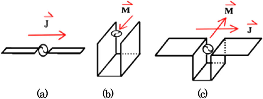
    Fig. 1. (a) Half-wavelength dipole antenna (electric dipole). (b) Quarter-wavelength short-circuit patch antenna (magnetic dipole). (c) ME dipole antenna.
    Configuration of LTCC ME dipole antenna: (a) simulation model, (b) top view, and (c) side view.
    Fig. 2. Configuration of LTCC ME dipole antenna: (a) simulation model, (b) top view, and (c) side view.
    Simulated |S11| versus (a) L, (b) d1, and (c) d2 for the antenna in Fig. 2.
    Fig. 3. Simulated |S11| versus (a) L, (b) d1, and (c) d2 for the antenna in Fig. 2.
    Current distribution at (a) 58 and (b) 67.3 GHz.
    Fig. 4. Current distribution at (a) 58 and (b) 67.3 GHz.
    Bandwidth and gain characteristics of the antenna in Fig. 2.
    Fig. 5. Bandwidth and gain characteristics of the antenna in Fig. 2.
    Configuration of the antenna array.
    Fig. 6. Configuration of the antenna array.
    Simulated S parameters of the T-junction power divider.
    Fig. 7. Simulated S parameters of the T-junction power divider.
    Simulated (a) E-plane and (b) H-plane couplings for antenna array.
    Fig. 8. Simulated (a) E-plane and (b) H-plane couplings for antenna array.
    Bandwidth and gain characteristics of the antenna array.
    Fig. 9. Bandwidth and gain characteristics of the antenna array.
    Radiation pattern of the antenna array at 58, 60, and 65 GHz: (a) E plane and (b) H plane.
    Fig. 10. Radiation pattern of the antenna array at 58, 60, and 65 GHz: (a) E plane and (b) H plane.
    Antenna TypeSize (mm3)Impedance BW (GHz)Peak Gain at 60 GHz
    Antenna-in-Package [17]12.5×8×1.26559–657 dBi
    Grid Array Antennas [18]15×15×0.656–67.516.5 dBi
    Vertical Off-Center dipole [19]16×14.7×1.256.2–65.815.6 dBi
    Our Work13.6×13.6×0.956.5–6817.67 dBi
    Table 1. Comparisons Between This Work and Other 60 GHz Dipole Antenna Arrays
    Zheng Guo, Huiping Tian, Xudong Wang, and Yuefeng Ji. Wide-bandwidth, high-gain, low-temperature cofired ceramic magneto-electric dipole antenna and arrays for millimeter wave radio-over-fiber systems[J]. Photonics Research, 2014, 2(4): B40
    Download Citation