Abstract
The designs of magneto-electric (ME) dipole antennas and 4 × 4 planar arrays on low-temperature cofired ceramic (LTCC) substrates are presented for radio-over-fiber (ROF) systems. The ME dipole antenna covers the four 2.16 GHz channels defined in the 60 GHz band from 57 to 66 GHz. It can be used as a 4 × 4 planar antenna array element for high gain performance. The results show that the proposed antenna array achieves a variation of peak gain from 15.0 to 18.1 dBi and a peak gain up to 17.67 dBi at 60 GHz. It is revealed that our design satisfies the 60 GHz standards ruled by IEEE 802.15.3c.1. INTRODUCTION
Recently, low-loss and high-speed wireless and wireline data transmission over fiber links has attracted increasing focus to radio-over-fiber (ROF) systems, which support not only voice and data but also many high-speed multimedia services, such as fast large-file transfer and real-time high-definition video [1]. Since the microwave bands applied in mobile cellular systems such as Global System for Mobile Communications (GSM) and Universal Mobile Telecommunications System (UMTS) cannot support high-data-rate traffic, millimeter wave bands have received more attention, for example, 60 GHz bands, which can provide a bandwidth of several GHz for these short-range communications. In addition, the communications in the 60 GHz band have some advantages, such as the possible miniaturization of the analog components and antennas and the possibility of frequency reuse over small distances because of the high attenuation by walls. In this connection, 60 GHz antennas have become a hot research topic.
60 GHz antennas designed with complementary metal-oxide semiconductor (CMOS) technology are popular due to the characteristic of miniaturization. However, most CMOS antennas would suffer from low gain performance [2]. Printed circuit broad technology has also been suggested, though they either lack stable radiation patterns [3] or narrow band antennas [4]. Compared with them, low-temperature cofired ceramic (LTCC) technology is particularly attractive because of its excellent high-frequency performance, compactness, light weight, and ease of integration [5–7]. The 60 GHz standards are defined according to IEEE 802.15.3c [8], which divides about 9 GHz of bandwidth from 57.24 to 65.88 GHz into four 2.16 GHz channels. Meanwhile, a gain of and stable radiation pattern are required for indoor wireless local area network communication systems. In order to meet these specifications, we propose the magneto-electric (ME) antennas, which have a good radiation pattern across the entire operating bandwidth due to their consisting of simultaneous electric and magnetic dipole excitations [9–11]. What is more, it is observed that the combination of LTCC and ME dipole antenna has both advantages.
In this paper, we present a ME dipole antenna on LTCC and use this kind of antenna to implement a array that has wide bandwidth and high gain. The bandwidth is broadened by the ME dipole and T feed at the stage of antenna unit design. The high gain is obtained by forming a planar antenna array. The antenna elements are fed by a quarter-wave matched T-junction feed network, which is placed between the top and the bottom grounds. The antenna array is optimized to have a bandwidth from 56.5 to 68 GHz, which can cover the 60 GHz band. In addition, a variation of peak gain from 15.0 to 18.1 dBi across the operating band and stable patterns are obtained.
Sign up for Photonics Research TOC. Get the latest issue of Photonics Research delivered right to you!Sign up now
2. LTCC ME DIPOLE ANTENNA
To excite both the electric dipole and magnetic dipole simultaneously, the amplitude and phase of the radiating sources have to be adjusted properly [12]. Therefore, the location and distance between electric dipole and magnetic dipole are of crucial importance. The principle of ME dipoles is shown as Fig. 1. Two horizontally oriented patches with identical current direction and intensity can lead to an electric dipole, as depicted in Fig. 1(a). Figure 1(b) is chosen as a magnetic dipole that is formed by the vertically oriented quarter-wavelength short-circuited patch antenna. While at a millimeter wave frequency, the shorted patches are very small and are often replaced by special metallic pins. Figure 1(c) is a combination of electric dipole and magnetic dipole [12–14].
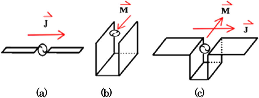
Figure 1.(a) Half-wavelength dipole antenna (electric dipole). (b) Quarter-wavelength short-circuit patch antenna (magnetic dipole). (c) ME dipole antenna.
The proposed ME dipole antenna for ROF systems is shown in Fig. 2. It entails two horizontally oriented patches forming an electric dipole and two vertically oriented parallel metallic pins shorted to the system ground plane to enable the quarter-wavelength patch antenna to form a magnetic dipole simultaneously. Ferro A6-M LTCC material with thickness of 0.1 mm for each layer, relative permittivity , loss , and conductor thickness of 0.01 mm was used as the substrate. The distance between the bottom and the top ground planes is of five-layer LTCC.

Figure 2.Configuration of LTCC ME dipole antenna: (a) simulation model, (b) top view, and (c) side view.
The study of patch length , T-feed diameter , and feeding circle diameter on impedance bandwidth is shown in Fig. 3. It is observed in Fig. 3(a) that only the first resonant frequency shifts slightly to the lower frequency with varied from 0.8 to 1.0 mm. Figure 3(b) presents both the first and the second resonant frequencies shift down with increasing. Figure 3(c) shows that when is varied from 0.10 to 0.14 mm, only the second resonant frequency shifts to the lower frequency. It can be concluded that the first resonance frequency is related to and and that the second resonance frequency depends on and . Good impedance matching is obtained with , , and .
Figure 3.Simulated versus (a) , (b) , and (c) for the antenna in Fig. 2.
To study the operating mechanism of the two resonances, the simulated current distributions at the first resonance frequency 58 GHz and the second resonance frequency 67.3 GHz are seen in Fig. 4. It is realized that the current distribution on the two horizontally oriented patches has almost identical direction and intensity, which illuminates the antenna as a dipole at these resonances. Figure 4(a) illustrates the current distribution at the first resonance. It flows mainly around the edge of the two radiating patches, T-feed, and stripline feed. While at the second resonance, as shown in Fig. 4(b), the current is quite weak on the two radiating patches compared with that around the stripline feed and T-feed, which is in good accordance with Fig. 3.
Figure 4.Current distribution at (a) 58 and (b) 67.3 GHz.
The bandwidth and gain of the antenna are shown in Fig. 5. The achieved bandwidth for is from 55.9 to 71.5 GHz, which is available for the 60 GHz band. In the whole working bandwidth, a variation of peak gain from 3.1 to 6.2 dBi is obtained. The maximum gain at 60 GHz is 4.53 dBi.
Figure 5.Bandwidth and gain characteristics of the antenna in Fig. 2.
3. LTCC ME DIPOLE ANTENNA ARRAY
In order to enhance the gain of the antenna, 16 ME dipole antenna units are designed to form a planar array, as seen in Fig. 6. The size of the array is . In order to make sure that the power from the incident port can be divided among the 16 units equally, a stripline network with T-junction is selected as the feed network [15]. Figure 7 describes the structure and S parameters of the T-junction power divider. All ports in the T-junction power divider are 50 Ω and all units in the port are excited in-phase. The matching at every port is obtained via a quarter-wave transformer. It is observed that simulated is better than , which means that little power is reflected by port 1. The insertion loss and have the same value that is about across the 60 GHz band (57–66 GHz). It is certified that the power from port 1 is divided between port 2 and port 3 equally. The design of the T-junction feed network can meet our requirements.
Figure 6.Configuration of the antenna array.
Figure 7.Simulated S parameters of the T-junction power divider.
When we design the antenna array, not only is the feed network considered to divide the power equally, but the mutual coupling between the adjacent antenna units should also be limited to as low as possible. Because the antenna array is used as a phase array, the scan angle is limited to . The distance between two adjacent antenna units can be calculated under the condition [16] where is desirable center frequency, is the speed of light in vacuum, and is the scan angle. In this case, the unit distance can be set at 3.2 mm. The antenna array is printed in the y-z-plane. As the monopoles are in the z direction, they are z polarized. Hence, the H plane for the antennas is the x-y plane and the E plane is the x-z plane. Simulated E- and H-plane couplings of two adjacent elements are shown in Fig. 8. The mutual coupling is less than for the E plane and for the H plane, which affects the impedance matching only slightly.
Figure 8.Simulated (a) E-plane and (b) H-plane couplings for antenna array.
The bandwidth and gain characteristics of the antenna array are presented in Fig. 9. The impedance bandwidth is available from 56.5 to 68 GHz. The peak gain varies from 15.0 to 18.1 dBi over the 60 GHz band (57–66 GHz). The bandwidth and gain characteristics of the ME dipole antenna can satisfy the 60 GHz standards ruled by IEEE 802.15.3c, which divides about 9 GHz bandwidth from 57.24 to 65.88 GHz into four 2.16 GHz channels and requires a gain of . Besides, a peak gain of 17.67 dBi at 60 GHz is obtained and the peak gain of the antenna array is 13.14 dB higher than that of the antenna unit. While the antenna gain drops abruptly above 66 GHz, this is because the ME dipole antenna is fed by a coplanar waveguide (CPW). The CPW-fed design can be replaced by probe-fed design to solve this problem [9].
Figure 9.Bandwidth and gain characteristics of the antenna array.
Figures 10(a) and 10(b) depict the E- and H-plane radiation patterns at the typical frequencies of 58, 60, and 65 GHz. The 3 dB beam widths are nearly identical, which shows the stability of the antenna array. What is more, at the typical frequencies, the pattern has a main beam fixing to the front direction and a back lobe of smaller than . The low back radiation levels are due to the complementary structure of the proposed ME dipole antenna array. A complementary structure is accomplished by exciting the orthogonally placed magnetic dipole and electric dipole with the same strength in magnitude.
Figure 10.Radiation pattern of the antenna array at 58, 60, and 65 GHz: (a) E plane and (b) H plane.
Table 1 lists comparisons of this work with other 60 GHz dipole antenna arrays on LTCC. It is revealed that the antenna in our work simultaneously obtains the characteristics of miniaturization, wide impedance bandwidth, and high peak gain at 60 GHz.
| Antenna Type | Size (mm3) | Impedance BW (GHz) | Peak Gain at 60 GHz |
|---|
| Antenna-in-Package [17] | 12.5×8×1.265 | 59–65 | 7 dBi |
| Grid Array Antennas [18] | 15×15×0.6 | 56–67.5 | 16.5 dBi |
| Vertical Off-Center dipole [19] | 16×14.7×1.2 | 56.2–65.8 | 15.6 dBi |
| Our Work | 13.6×13.6×0.9 | 56.5–68 | 17.67 dBi |
Table 1. Comparisons Between This Work and Other 60 GHz Dipole Antenna Arrays
4. CONCLUSION
In this paper, a ME dipole antenna that entails two horizontally oriented patches, two vertically oriented parallel metallic pins shorted to the top ground plane, and T-feed was proposed to achieve wide impedance bandwidth for 60 GHz applications. In order to mitigate severe path loss at 60 GHz, a planar antenna array was designed. The results showed that the unlicensed frequency band of 57–66 GHz could be covered and a peak gain of 17.67 dBi at 60 GHz was obtained. Compared with other 60 GHz antenna arrays on LTCC, wide bandwidth and high gain are obtained. In addition, the patch array is suitable for short-range communications and convenient for integration in the 60 GHz spectrum. It will find potential applications in ROF systems.
References
[1] H. Lu, H. Peng, W. Tsai, C. Lin, S. Tzeng, Y. Lin. Bidirectional hybrid CATV/radio-over-fiber WDM transport system. Opt. Lett., 35, 279-281(2010).
[2] X. Bao, Y. Guo, Y. Xiong. 60-GHz AMC-based circularly polarized on-chip antenna using standard 0.18-m CMOS technology. IEEE Trans. Antennas Propag., 60, 2234-2241(2012).
[3] A. Grbic, G. V. Eleftheriades. Leaky CPW-based slot antenna arrays for millimeter-wave applications. IEEE Trans. Antennas Propag., 50, 1494-1504(2002).
[4] C. H. Tseng, C. J. Chen, T. H. Chu. A low-cost 60-GHz switched beam patch antenna array with Butler matrix network. IEEE Antennas Wireless Propag. Lett., 7, 432-435(2008).
[5] R. R. Tummala, M. Swaminathan, M. M. Tentzeris, J. Laskar, G.-K. Chang, S. Sitaraman, D. Keezer, D. Guidotti, Z. R. Huang, K. Lim, L. X. Wan, S. K. Bhattacharya, V. Sundaram, F. H. Liu, P. M. Raj. The SOP for miniaturized, mixed-signal computing, communication, and consumer systems of the next decade. IEEE Trans. Adv. Packag., 27, 250-267(2004).
[6] C. R. Liu, Y. X. Guo, X. Y. Bao, S. Q. Xiao. 60-GHz LTCC integrated circularly polarized helical antenna array. IEEE Trans. Antennas Propag., 60, 1329-1335(2012).
[7] H. Sun, Y. X. Guo, Z. Wang. 60-GHz circularly polarized U-slot patch antenna array on LTCC. IEEE Trans. Antennas Propag., 61, 430-435(2013).
[8] (2009).
[9] K. Luk, M. Li. Magneto-electric dipole antennas for millimeter-wave applications. Proceedings of Asia-Pacific Microwave Conference, 304-306(2013).
[10] K. B. Ng, H. Wong, K. K. So, C. H. Chan, K. M. Luk. 60 GHz plated through hole printed magneto-electric dipole antenna. IEEE Trans. Antennas Propag., 60, 3129-3136(2012).
[11] Z. Guo, H. Tian, Q. Luo, X. Wang, Y. Ji. EBG ME-dipole antenna with enhanced gain for intelligent radio-over-fiber systems. Proceedings of 12th International Conference on Optical Communications and Networks, 1-3(2013).
[12] K.-M. Luk, H. Wong. A new wideband unidirectional antenna element. Int. J. Microwave Opt. Technol., 1, 35-44(2006).
[13] B. Q. Wu, K.-M. Luk. A broadband dual-polarized magneto-electric dipole antenna with simple feeds. IEEE Antennas Wireless Propag. Lett., 8, 60-63(2009).
[14] L. Siu, H. Wong, K.-M. Luk. A dual-polarized magneto-electric dipole with dielectric loading. IEEE Trans. Antennas Propag., 57, 616-623(2009).
[15] A. E. I. Lamminen, J. Säily, A. R. Vimpari. 60-GHz patch antennas and arrays on LTCC with embedded-cavity substrates. IEEE Trans. Antennas Propag., 56, 2865-2874(2008).
[16] R. J. Mailloux. Phased Array Antenna Handbook(1994).
[17] Y. P. Zhang, M. Sun, K. M. Chua, L. L. Wai, D. Liu. Antenna-in-package design for wirebond interconnection to highly integrated 60-GHz radios. IEEE Trans. Antennas Propag., 57, 2842-2852(2009).
[18] B. Zhang, Y. P. Zhang. Grid array antennas with subarrays and multiple feeds for 60-GHz radios. IEEE Trans. Antennas Propag., 60, 2270-2275(2012).
[19] H. Chu, Y. X. Guo, Z. Wang. 60-GHz LTCC wideband vertical off-center dipole antenna and arrays. IEEE Trans. Antennas Propag., 61, 153-161(2013).

