• Acta Optica Sinica
  • Vol. 37, Issue 10, 1013001 (2017)
Zichun Le1, Zili Xu1, Chen Sun1, Ying Du1, and Wen Dong2、*
Author Affiliations
  • 1 College of Sciences, Zhejiang University of Technology, Hangzhou, Zhejiang 310023, China
  • 2 College of Environment, Zhejiang University of Technology, Hangzhou, Zhejiang 310014, China
  • show less
    DOI: 10.3788/AOS201737.1013001 Cite this Article Set citation alerts
    Zichun Le, Zili Xu, Chen Sun, Ying Du, Wen Dong. Design and Simulation of Elliptical Crossing Waveguide Based on Multimode Interference[J]. Acta Optica Sinica, 2017, 37(10): 1013001 Copy Citation Text show less
    Construction of elliptical MMI
    Fig. 1. Construction of elliptical MMI
    Simulation of traditional elliptical MMI crossing waveguide
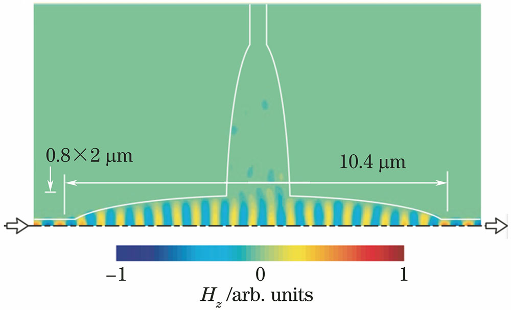
    Fig. 2. Simulation of traditional elliptical MMI crossing waveguide
    Crossing structure of new elliptical MMI based on SOI
    Fig. 3. Crossing structure of new elliptical MMI based on SOI
    Simulated optical field distribution of new elliptical MMI crossing waveguide
    Fig. 4. Simulated optical field distribution of new elliptical MMI crossing waveguide
    (a) First position of self-focusing of elliptical MMI; (b) first position of self-imaging of rectangle MMI; (c) sixth position of self-focusing of elliptical MMI
    Fig. 5. (a) First position of self-focusing of elliptical MMI; (b) first position of self-imaging of rectangle MMI; (c) sixth position of self-focusing of elliptical MMI
    Design of elliptical MMI crossing size. (a) W1=0.45 μm; (b) W1=0.5 μm
    Fig. 6. Design of elliptical MMI crossing size. (a) W1=0.45 μm; (b) W1=0.5 μm
    Simulated optical field distribution of elliptical MMI crossing waveguide optimized. (a) W1=0.45 μm; (b) W1=0.5 μm
    Fig. 7. Simulated optical field distribution of elliptical MMI crossing waveguide optimized. (a) W1=0.45 μm; (b) W1=0.5 μm
    Electric field model distribution for W1=0.45 μm. (a) Transverse; (b) longitudinal
    Fig. 8. Electric field model distribution for W1=0.45 μm. (a) Transverse; (b) longitudinal
    Electric field model distribution for W1=0.5 μm. (a) Transverse; (b) longitudinal
    Fig. 9. Electric field model distribution for W1=0.5 μm. (a) Transverse; (b) longitudinal
    Loss and crosstalk characteristics of elliptical MMI crossing waveguide for W1=0.45 μm. (a) Single loss; (b) single crosstalk
    Fig. 10. Loss and crosstalk characteristics of elliptical MMI crossing waveguide for W1=0.45 μm. (a) Single loss; (b) single crosstalk
    Loss and crosstalk characteristics of elliptical MMI crossing waveguide for W1=0.5 μm. (a) Single loss; (b) single crosstalk
    Fig. 11. Loss and crosstalk characteristics of elliptical MMI crossing waveguide for W1=0.5 μm. (a) Single loss; (b) single crosstalk
    Approximate methodβ0β1β2β3β4β5
    Characteristic equation11.4511.1210.569.7338.5887.049
    Dispersion equation11.4511.1210.559.7008.4826.699
    Paraxial approximation11.4511.1310.599.8498.8907.719
    Table 1. Propagation constants derived from three approximate methods μm-1
    Zichun Le, Zili Xu, Chen Sun, Ying Du, Wen Dong. Design and Simulation of Elliptical Crossing Waveguide Based on Multimode Interference[J]. Acta Optica Sinica, 2017, 37(10): 1013001
    Download Citation