
Xiao Wang, Yuliang Liu, liyan Li. Symmetry-Based Projective Algorithm for 3D Localization of Small Target at a Wide Field of View[J]. Acta Optica Sinica, 2020, 40(10): 1015001
- Acta Optica Sinica
- Vol. 40, Issue 10, 1015001 (2020)
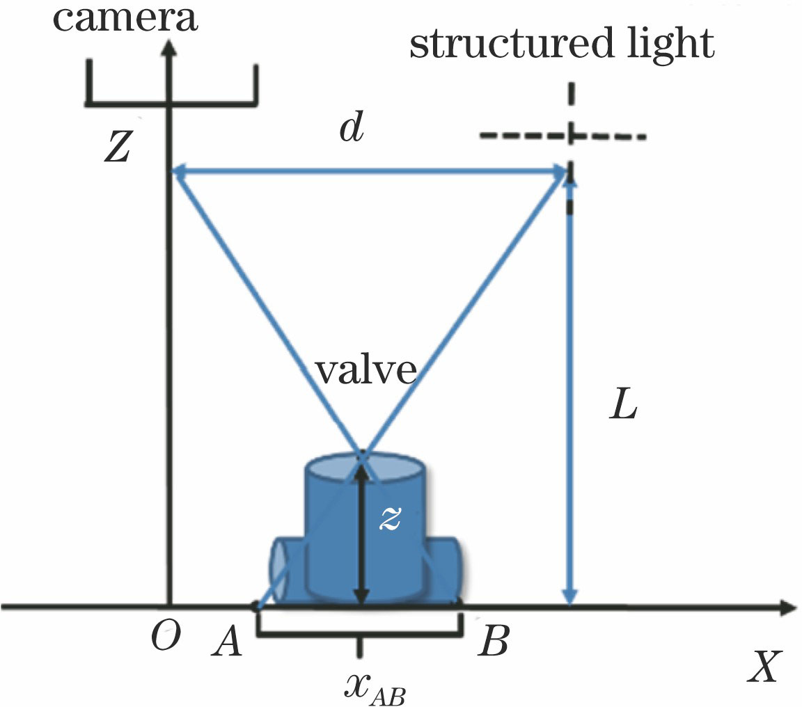
Fig. 1. Schematic diagram of structured light system based on fringe projection
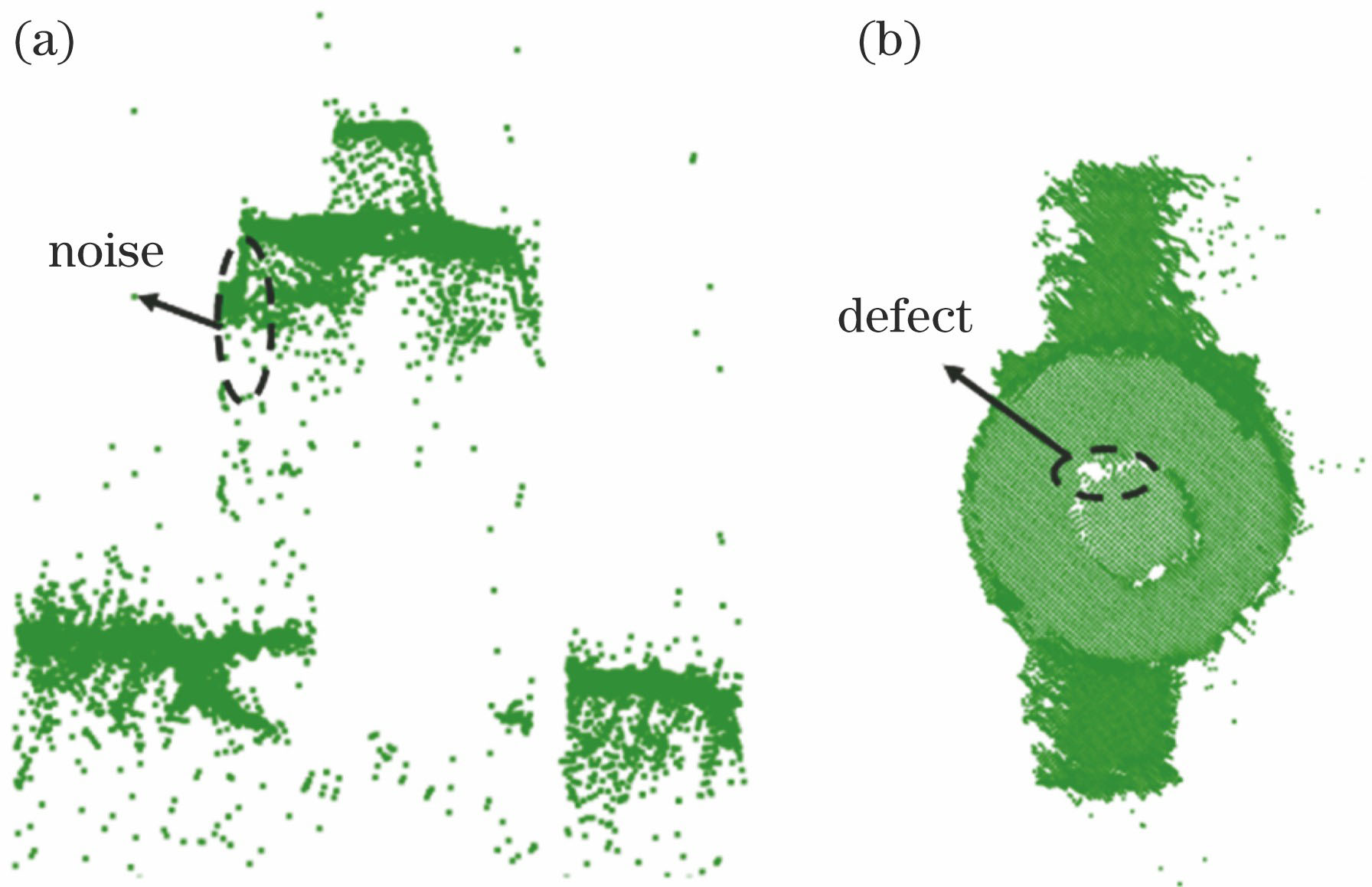
Fig. 2. Point cloud data of valve. (a) Front view; (b) top view
Fig. 3. Cylinder valve. (a) Physical map; (b) sketch map
Fig. 4. Exact position for coordinate P and pose Q
Fig. 5. Calculation pose Q. (a) QF-2/QF-2C; (b) YSF-1
Fig. 6. Schematic diagram of each position in valve
Fig. 7. Calculation coordinate P*. (a) QF-2/QF-2C; (b) YSF-1
Fig. 8. Overall flow chart of the algorithm
Fig. 9. Valve in experimental scene
Fig. 10. Edge detection result with Canny algorithm
Fig. 11. Discrimination of detection accuracy
Fig. 12. Pre-processing. (a) Initial localization; (b) segmentation result
Fig. 13. Algorithm performance for defective data. (a) Reflection; (b) incomplete shooting
Fig. 14. Coordinate error results for different algorithms
|
Table 1. 3D camera performance parameters
|
Table 2. Distribution of orientation errors
|
Table 3. Distribution of coordinate errors
|
Table 4. Coordinate errors for situation (a)&(b)

Set citation alerts for the article
Please enter your email address
© Copyright 2018-2021 | Chinese Laser Press. All Rights Reserved 沪ICP备15018463号-20