
Yunxiu Shui, Lin Hu, Yaohui Dai, Haiyu Wu, Gang Zhu, Yan Yang. Three-Dimensional Display of Rotary Mechanical Parts Based on Digital Holography[J]. Laser & Optoelectronics Progress, 2020, 57(6): 060901
- Laser & Optoelectronics Progress
- Vol. 57, Issue 6, 060901 (2020)
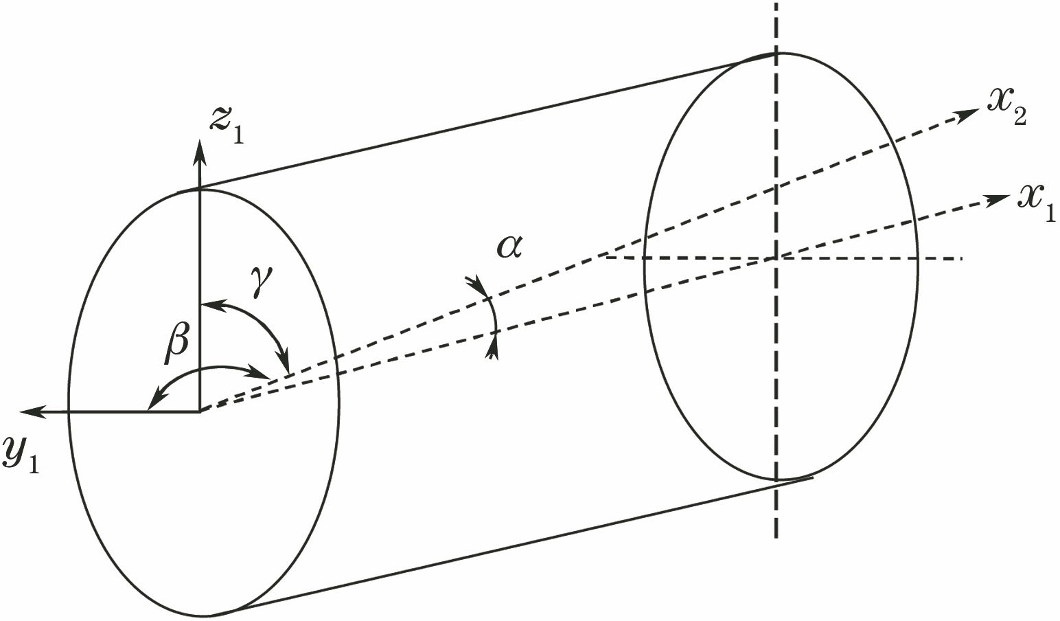
Fig. 1. Two cylindrical coordinates with uncoincident axes
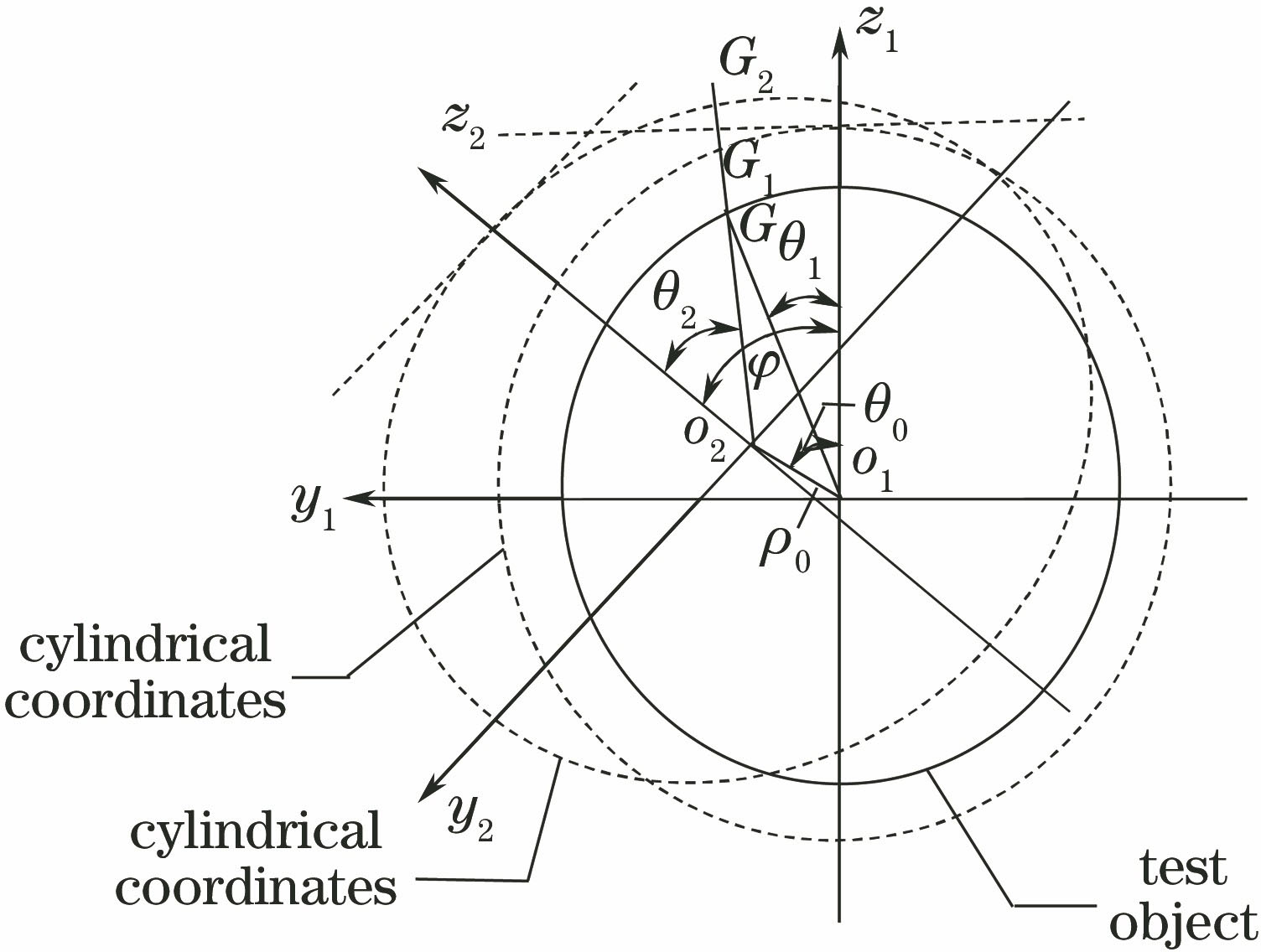
Fig. 2. Coordinate transformation relations in cylindrical coordinate systems
Fig. 3. Particle swarm optimization solution flow chart
Fig. 4. Experimental optical path of inclined illumination light measurement
Fig. 5. Experimental setup for measuring inclined illumination light
Fig. 6. Reconstruction results of specular and diffuse reflection. (a) Result of specular reflection on 1-FFT plane; (b) reconstruction of specular reflection image after filtering; (c) result of diffuse reflection on 1-FFT plane; (d) reconstruction of diffuse reflection image after filtering
Fig. 7. Flow of +1st-order image marking method on the 1-FFT reconstructed image plane
Fig. 8. Effect of gradual specular reflection weakening. (a) Strong specular reflection; (b) weakened specular reflection; (c) simultaneous existence; (d) diffuse reflection
Fig. 9. One object with a height difference of 9 mm, combined by two gauge blocks
Fig. 10. Height of measuring block by inclined illumination method. (a) Digital hologram; (b) 1-FFT reconstruction image; (c) FIMG4FFT reconstruction image; (d) phase difference image; (e) image with linear tilt terms removed; (f) image after denoising
Fig. 11. Contour image of the box in Fig. 10 (f)
Fig. 12. Curve corresponding to the line in Fig. 10 (f)
Fig. 13. Stud contour measured by inclined light illumination method. (a) Digital hologram; (b) 1-FFT reconstruction image; (c) FIMG4FFT reconstruction image; (d) phase difference image; (e) image with linear tilt terms removed; (f) image after denoising
Fig. 14. Three-dimensional phase distribution of studs at each viewing angle. (a) 0°; (b) 90°; (c) 180°; (d) 270°
Fig. 15. Three-dimensional topography after stud splicing

Set citation alerts for the article
Please enter your email address
© Copyright 2018-2021 | Chinese Laser Press. All Rights Reserved 沪ICP备15018463号-20