• Laser & Optoelectronics Progress
  • Vol. 56, Issue 20, 202411 (2019)
Huili Wang1、2, Jun Qin1、2, Tongtong Kang1、2, Yan Zhang1、2, Lixia Nie1、2, Wansen Ai1、2, Yanfang Li1、2, and Lei Bi1、2、*
Author Affiliations
  • 1National Engineering Research Center of Electromagnetic Radiation Control Material, University of Electronic Science and Technology of China, Chengdu, Sichuan 610054, China
  • 2School of Electronic Science and Engineering, University of Electronic Science and Technology of China, Chengdu, Sichuan 610054, China
  • show less
    DOI: 10.3788/LOP56.202411 Cite this Article Set citation alerts
    Huili Wang, Jun Qin, Tongtong Kang, Yan Zhang, Lixia Nie, Wansen Ai, Yanfang Li, Lei Bi. Magneto-Optical Surface Plasmon Resonance and Refractive Index Sensor Based on Au/Ce∶YIG/TiN Structure[J]. Laser & Optoelectronics Progress, 2019, 56(20): 202411 Copy Citation Text show less
    Schematic of device structure
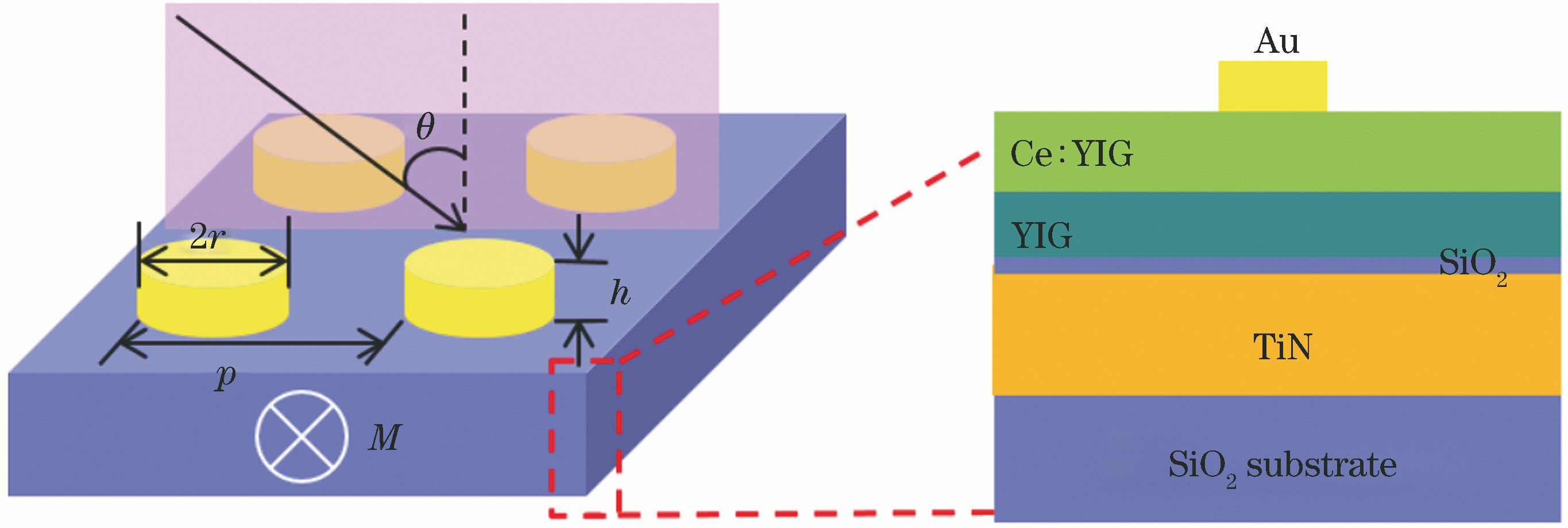
    Fig. 1. Schematic of device structure
    Reflectivity as a function of r, h, p, θ, and wavelength. (a) Reflectivity versus r when h=30 nm, p=600 nm, and θ=45°; (b) reflectivity versus h when r=70 nm, p=600 nm, and θ=45°;(c) reflectivity versus p when r=70 nm, h=30 nm, and θ=45°;(d) reflectivity versus θ when r=70 nm, h=30 nm, and p=650 nm
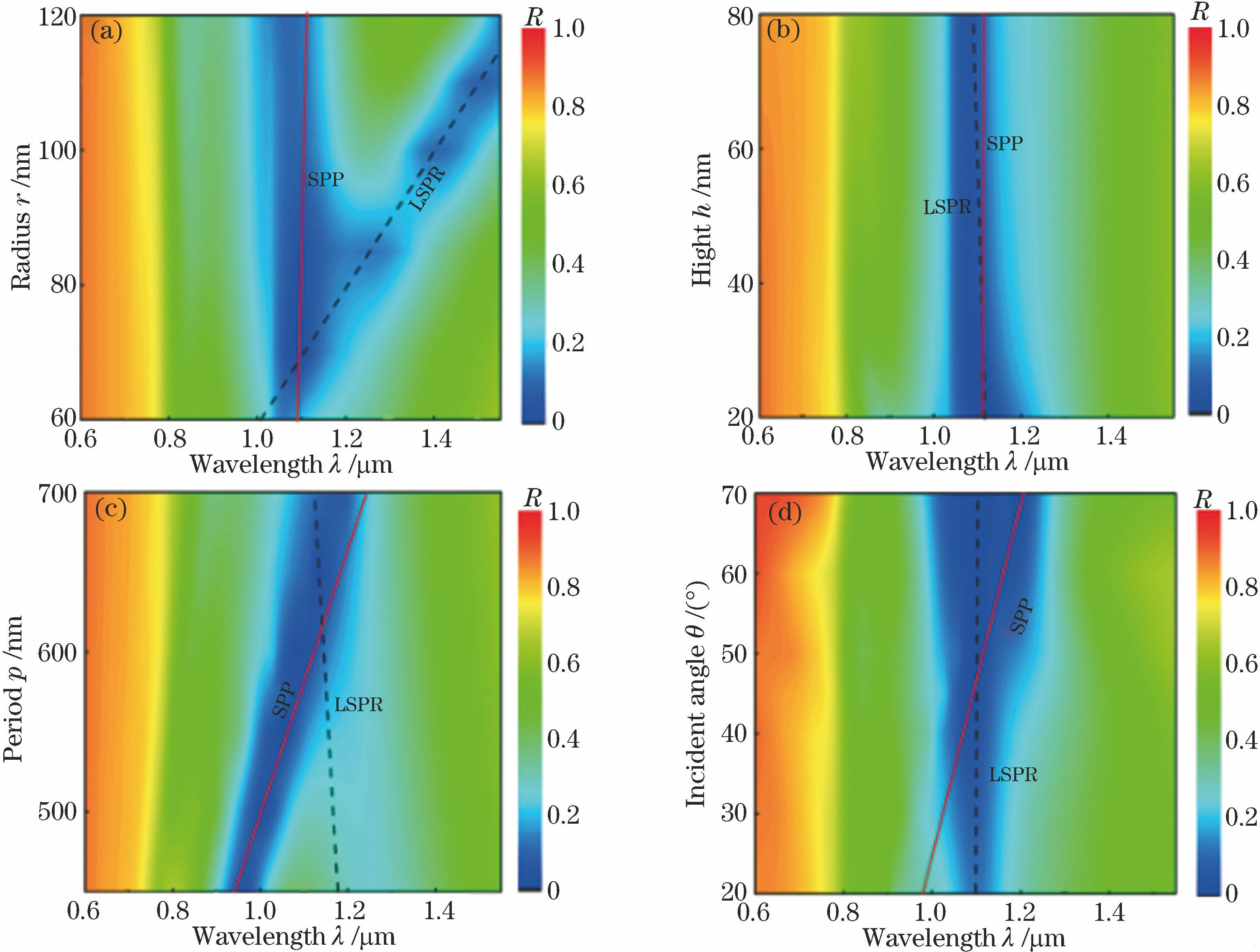
    Fig. 2. Reflectivity as a function of r, h, p, θ, and wavelength. (a) Reflectivity versus r when h=30 nm, p=600 nm, and θ=45°; (b) reflectivity versus h when r=70 nm, p=600 nm, and θ=45°;(c) reflectivity versus p when r=70 nm, h=30 nm, and θ=45°;(d) reflectivity versus θ when r=70 nm, h=30 nm, and p=650 nm
    Cross-section of device and magnetic field H distributions under different structural parameters. (a) Cross-section of xoz plane of device when r=100 nm; (b) SPP mode;(c) LSPR mode; (d) coupling mode when r=70 nm
    Fig. 3. Cross-section of device and magnetic field H distributions under different structural parameters. (a) Cross-section of xoz plane of device when r=100 nm; (b) SPP mode;(c) LSPR mode; (d) coupling mode when r=70 nm
    TMOKE as a function of r, h, p, θ, and wavelength. (a) TMOKE versus r when h=30 nm, p=600 nm, and θ=45°; (b) TMOKE versus h when r=70 nm, p=600 nm, and θ=45°;(c) TMOKE versus p when r=70 nm, h=30 nm, and θ=45°; (d) TMOKE versus θ when r=70 nm, h=30 nm, and p=650 nm
    Fig. 4. TMOKE as a function of r, h, p, θ, and wavelength. (a) TMOKE versus r when h=30 nm, p=600 nm, and θ=45°; (b) TMOKE versus h when r=70 nm, p=600 nm, and θ=45°;(c) TMOKE versus p when r=70 nm, h=30 nm, and θ=45°; (d) TMOKE versus θ when r=70 nm, h=30 nm, and p=650 nm
    Refractive index sensing performance of the device. (a) Change of TMOKE at different refractive indexes; (b) change of peak position at different refractive indexes
    Fig. 5. Refractive index sensing performance of the device. (a) Change of TMOKE at different refractive indexes; (b) change of peak position at different refractive indexes
    n /RIU1.0001.0021.0041.0061.0081.010
    Γ /nm0.82670.53240.22670.55411.12001.8900
    FoM /RIU-1601.3548933.77162192.4586897.1962443.8750263.0370
    Table 1. Line width and FoM of sensing signal of the device at different refractive indexes
    Huili Wang, Jun Qin, Tongtong Kang, Yan Zhang, Lixia Nie, Wansen Ai, Yanfang Li, Lei Bi. Magneto-Optical Surface Plasmon Resonance and Refractive Index Sensor Based on Au/Ce∶YIG/TiN Structure[J]. Laser & Optoelectronics Progress, 2019, 56(20): 202411
    Download Citation