
Genyu Chen, Peixin Zhong, Shaoxiang Cheng. Coupling Behavior Between Glass Frit and Plate During Laser-Assisted Glass Frit Bonding[J]. Chinese Journal of Lasers, 2021, 48(18): 1802005
- Chinese Journal of Lasers
- Vol. 48, Issue 18, 1802005 (2021)
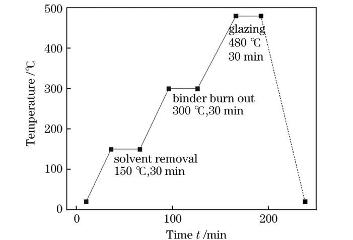
Fig. 1. Heating process curve
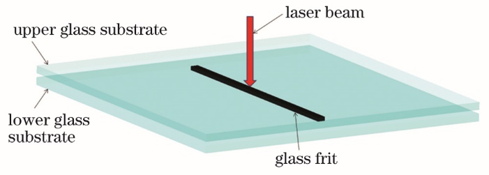
Fig. 2. Schematic of laser-assisted glass frit bonding
Fig. 3. Laser-assisted glass frit bonding apparatus diagram
Fig. 4. Schematic of coupling behavior during laser-assisted glass frit bonding
Fig. 5. Observed images of typical coupling behavior. (a) The glass coating area is not fully connected; (b) the glass coating area is fully connected; (c) bonding area expansion
Fig. 6. Images of weld seam after connection. (a) The glass coating area is not fully connected; (b) the glass coating area is fully connected; (c) bonding area expansion
Fig. 7. Formation of impurity-type pores. (a) t0; (b) t0+33 ms; (c) t0+133 ms; (d) t0+600 ms
Fig. 8. Formation of impurity-type pores when the impurity particles are large.(a) t0; (b) t0+50 ms; (c) t0+667 ms
Fig. 9. Formation of intensive and impurity-type pores. (a) t0; (b) t0+1350 ms; (c) t0+1650 ms
Fig. 10. Movement direction of impurity-type pores. (a) t0; (b) t0+116 ms; (c) t0+500 ms
Fig. 11. Movement direction of impurity-type pores under special circumstances. (a) t0; (b) t0+417 ms; (c) t0+567 ms; (d) t0+783 ms;(e) t0+933 ms; (f) t0+1483 ms
Fig. 12. Area of impurity-type pore changes curve with time during the process of pore overflow
Fig. 13. Other common defects. (a) Partially prominent bonding area; (b) partially not connected
|
Table 1. Thermal properties of material used in the study
|
Table 2. Process parameters of typical coupling behavior

Set citation alerts for the article
Please enter your email address
© Copyright 2018-2021 | Chinese Laser Press. All Rights Reserved 沪ICP备15018463号-20