• Photonics Research
  • Vol. 9, Issue 8, 1423 (2021)
Xin-Tao He1、2、†, Meng-Yu Li1、2、†, Hao-Yang Qiu1、2, Wen-Sheng Ruan1、2, Li-Dan Zhou1, Lin Liu1, Xiao-Dong Chen1、2, Wen-Jie Chen1、2, Fu-Li Zhao1、2, and Jian-Wen Dong1、2、*
Author Affiliations
  • 1State Key Laboratory of Optoelectronic Materials and Technologies, Sun Yat-sen University, Guangzhou 510275, China
  • 2School of Physics, Sun Yat-sen University, Guangzhou 510275, China
  • show less
    DOI: 10.1364/PRJ.419569 Cite this Article Set citation alerts
    Xin-Tao He, Meng-Yu Li, Hao-Yang Qiu, Wen-Sheng Ruan, Li-Dan Zhou, Lin Liu, Xiao-Dong Chen, Wen-Jie Chen, Fu-Li Zhao, Jian-Wen Dong. In-plane excitation of a topological nanophotonic corner state at telecom wavelengths in a cross-coupled cavity[J]. Photonics Research, 2021, 9(8): 1423 Copy Citation Text show less
    2D Su–Schrieffer–Heeger (SSH) model to describe SOTPCs with four square-holes clusters. To shrink/expand the clusters to the center/corner of unit cell, the structure will generate inequivalent inter-intra hopping (ta≠tb). The shrunken structure (blue) is dominant for intra-cluster hopping (ta>tb) with trivial topology, while the expanded case (red) is for inter-cluster hopping (ta<tb) with nontrivial topology.
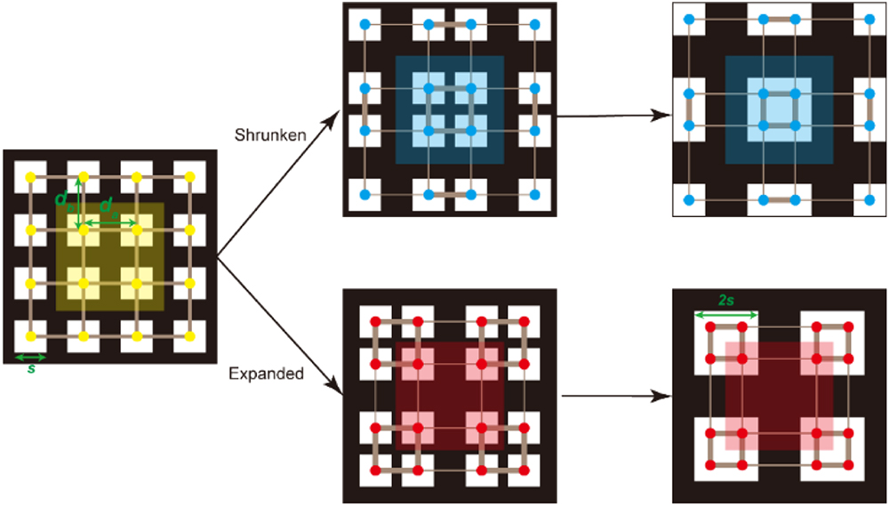
    Fig. 1. 2D Su–Schrieffer–Heeger (SSH) model to describe SOTPCs with four square-holes clusters. To shrink/expand the clusters to the center/corner of unit cell, the structure will generate inequivalent inter-intra hopping (tatb). The shrunken structure (blue) is dominant for intra-cluster hopping (ta>tb) with trivial topology, while the expanded case (red) is for inter-cluster hopping (ta<tb) with nontrivial topology.
    Bulk states of SOTPC in a silicon membrane. (a) 3D schematic of the designed SOTPC in free-standing silicon membrane with 220 nm thickness. It can be viewed as a dielectric-vein PC in a square lattice with the periodicity a=430 nm and the side length of square holes 2s=266 nm. (b) TE-like band structure of SOTPC, showing a 13.2% TE-like gap from 1274 to 1454 nm (yellow). (c)–(d) Expectation values of mirror-flip operation for shrunken PC and expanded PC eigenmodes along ΓX (circle) and ΓY (asterisk) directions. ηx (ηy) represents the expectation values of mirror-flip operation with respect to x=0 (y=0) plane.
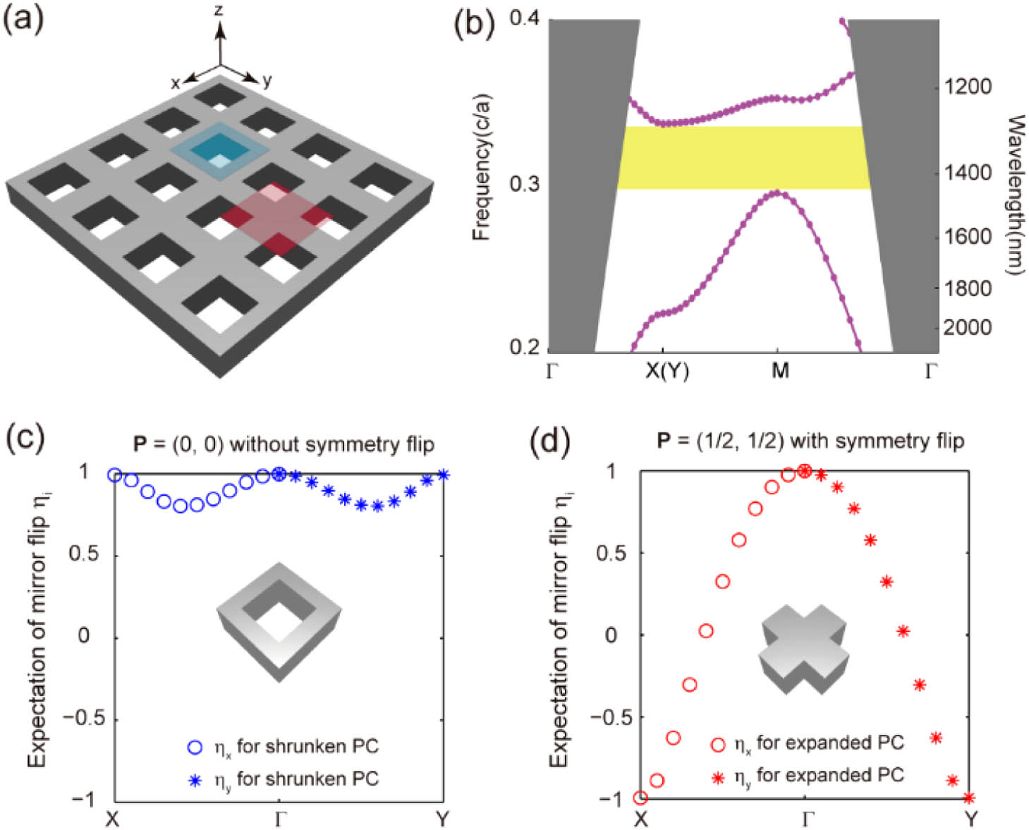
    Fig. 2. Bulk states of SOTPC in a silicon membrane. (a) 3D schematic of the designed SOTPC in free-standing silicon membrane with 220 nm thickness. It can be viewed as a dielectric-vein PC in a square lattice with the periodicity a=430  nm and the side length of square holes 2s=266  nm. (b) TE-like band structure of SOTPC, showing a 13.2% TE-like gap from 1274 to 1454 nm (yellow). (c)–(d) Expectation values of mirror-flip operation for shrunken PC and expanded PC eigenmodes along ΓX (circle) and ΓY (asterisk) directions. ηx (ηy) represents the expectation values of mirror-flip operation with respect to x=0 (y=0) plane.
    Localized cavity mode based on topological corner state in a 90 deg bend interface. (a) Schematic illustration of a bend interface constructed by shrunken (blue) and expanded (red) PCs. (b) Photonic LDOS spectrum at the corner point of the bend interface, which is normalized by the LDOS in vacuum. (c) Hz field patterns of corner states for the z center (z=0) and y center (y=0) planes, excited by a dipole source at the corner point at resonant wavelength (λ=1400.515 nm). (d) 2D spatial Fourier transformation (FT) of Hz at the z center plane. The green solid box and dashed circle are the first Brillouin zone and light cone of air, respectively.
    Fig. 3. Localized cavity mode based on topological corner state in a 90 deg bend interface. (a) Schematic illustration of a bend interface constructed by shrunken (blue) and expanded (red) PCs. (b) Photonic LDOS spectrum at the corner point of the bend interface, which is normalized by the LDOS in vacuum. (c) Hz field patterns of corner states for the z center (z=0) and y center (y=0) planes, excited by a dipole source at the corner point at resonant wavelength (λ=1400.515  nm). (d) 2D spatial Fourier transformation (FT) of Hz at the z center plane. The green solid box and dashed circle are the first Brillouin zone and light cone of air, respectively.
    Experimental observation of nanophotonic corner states through far-field images. (a) Schematic view and (b) SEM images of cross-coupled cavity based on the bend interface of SOTPC. Note that some edge rectangular holes are filled with silicon to form a line-defect photonic crystal waveguide. (c) Far-field images of bulk, edge, and corner states in a cross-coupled cavity sample via an optical microscope system. (d) Simulated field patterns of electromagnetic energy of bulk, edge, and corner states at the z center plane.
    Fig. 4. Experimental observation of nanophotonic corner states through far-field images. (a) Schematic view and (b) SEM images of cross-coupled cavity based on the bend interface of SOTPC. Note that some edge rectangular holes are filled with silicon to form a line-defect photonic crystal waveguide. (c) Far-field images of bulk, edge, and corner states in a cross-coupled cavity sample via an optical microscope system. (d) Simulated field patterns of electromagnetic energy of bulk, edge, and corner states at the z center plane.
    Measurement of transmission spectra and Q factor in a cross-coupled cavity. (a) Description of cross-coupled cavity mode by temporal CMT with Lorentz feature. (b) Simulated transmittance (red dots) and Lorentz fitting (green line) of cross-coupled cavity, that retrieve the resonant wavelength λC=1400.459 nm, the out-of-plane radiative quality factor Qr=8994, and the in-plane coupling quality factor Qw=11,069 for the designed cavity. (c) SEM images of fabricated samples and (d) measured transmission spectra for bulk crystal, flat interface, and cross-coupled cavity, respectively. The resonant peak near 1383 nm is in correspondence with topological corner state. (e) Measured transmission spectrum (red) of cross-coupled cavity around the resonant wavelength, normalized by the transmission spectrum of a line-defect PC waveguide.
    Fig. 5. Measurement of transmission spectra and Q factor in a cross-coupled cavity. (a) Description of cross-coupled cavity mode by temporal CMT with Lorentz feature. (b) Simulated transmittance (red dots) and Lorentz fitting (green line) of cross-coupled cavity, that retrieve the resonant wavelength λC=1400.459  nm, the out-of-plane radiative quality factor Qr=8994, and the in-plane coupling quality factor Qw=11,069 for the designed cavity. (c) SEM images of fabricated samples and (d) measured transmission spectra for bulk crystal, flat interface, and cross-coupled cavity, respectively. The resonant peak near 1383 nm is in correspondence with topological corner state. (e) Measured transmission spectrum (red) of cross-coupled cavity around the resonant wavelength, normalized by the transmission spectrum of a line-defect PC waveguide.
    Schematic diagram of the experimental setup.
    Fig. 6. Schematic diagram of the experimental setup.
    Evolution of photonic band structures with cluster shrinkage/expansion. (a) Schematic view of the photonic crystal unit cell, consisting of four air-hole clusters. (b)–(d) TE band structures with different intra-cluster distance.
    Fig. 7. Evolution of photonic band structures with cluster shrinkage/expansion. (a) Schematic view of the photonic crystal unit cell, consisting of four air-hole clusters. (b)–(d) TE band structures with different intra-cluster distance.
    Far-field images of cross-coupled cavity, under in-plane excitation of (a) bulk state at λ=1269 nm, (b) corner state at λ=1383.033 nm, (c) edge state at λ=1440 nm and without eigenmode excitation of PC slab (d) at λ=1301 nm and (e) at the resonant wavelength, respectively.
    Fig. 8. Far-field images of cross-coupled cavity, under in-plane excitation of (a) bulk state at λ=1269  nm, (b) corner state at λ=1383.033  nm, (c) edge state at λ=1440  nm and without eigenmode excitation of PC slab (d) at λ=1301  nm and (e) at the resonant wavelength, respectively.
    Xin-Tao He, Meng-Yu Li, Hao-Yang Qiu, Wen-Sheng Ruan, Li-Dan Zhou, Lin Liu, Xiao-Dong Chen, Wen-Jie Chen, Fu-Li Zhao, Jian-Wen Dong. In-plane excitation of a topological nanophotonic corner state at telecom wavelengths in a cross-coupled cavity[J]. Photonics Research, 2021, 9(8): 1423
    Download Citation