• Advanced Photonics
  • Vol. 5, Issue 6, 066002 (2023)
Jingya Xie1, Jun Qian1, Tengjiao Wang1, Linjie Zhou2、*, Xiaofei Zang1, Lin Chen1, Yiming Zhu1、*, and Songlin Zhuang1
Author Affiliations
  • 1University of Shanghai for Science and Technology, Terahertz Technology Innovation Research Institute, Shanghai Key Laboratory of Modern Optical System, Shanghai, China
  • 2Shanghai Jiao Tong University, State Key Laboratory of Advanced Optical Communication Systems and Networks, Department of Electronic Engineering, Shanghai, China
  • show less
    DOI: 10.1117/1.AP.5.6.066002 Cite this Article Set citation alerts
    Jingya Xie, Jun Qian, Tengjiao Wang, Linjie Zhou, Xiaofei Zang, Lin Chen, Yiming Zhu, Songlin Zhuang. Integrated terahertz vortex beam emitter for rotating target detection[J]. Advanced Photonics, 2023, 5(6): 066002 Copy Citation Text show less
    Illustration of the concepts. (a) Schematic of the designed integrated THz vortex beam emitter. The insets depict the geometry of the waveguide cross section and grating scatterers, which are all cuboid in shape. (b) Optical microscope images of the fabricated device. The inset is a zoomed-in view of the grating scatterers and the coupling section between the bus waveguide and the resonator. (c) Schematic of rotational Doppler effect. A tiny scatterer from a rotating body is taken out to analyze the relationship between the Poynting vector and the scatterer velocity on the condition of coaxial incidence. pφ→ and pz→ are the angular and the propagation components, respectively.
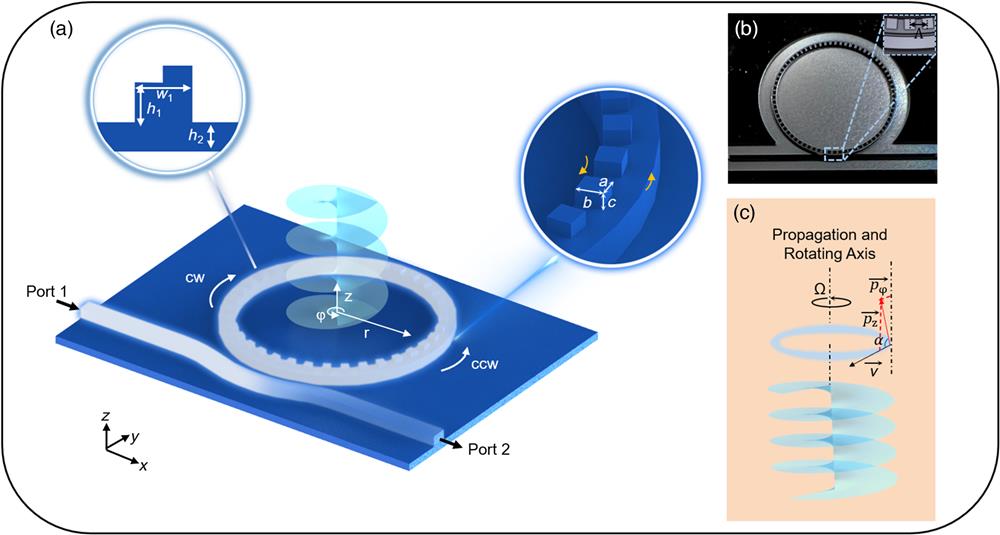
    Fig. 1. Illustration of the concepts. (a) Schematic of the designed integrated THz vortex beam emitter. The insets depict the geometry of the waveguide cross section and grating scatterers, which are all cuboid in shape. (b) Optical microscope images of the fabricated device. The inset is a zoomed-in view of the grating scatterers and the coupling section between the bus waveguide and the resonator. (c) Schematic of rotational Doppler effect. A tiny scatterer from a rotating body is taken out to analyze the relationship between the Poynting vector and the scatterer velocity on the condition of coaxial incidence. pφ and pz are the angular and the propagation components, respectively.
    (a) Measured transmission spectrum of the THz vortex emitter for the TE mode. Note that the black annotation indicates the topological charge lTC. The orange region represents the frequency range used for near-field and rotational Doppler experiments. (b) Experimental setup for device near-field characterization.
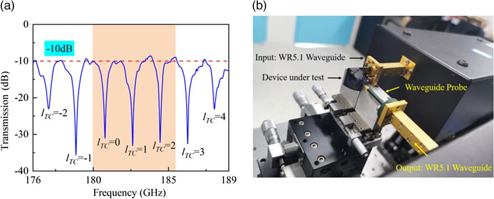
    Fig. 2. (a) Measured transmission spectrum of the THz vortex emitter for the TE mode. Note that the black annotation indicates the topological charge lTC. The orange region represents the frequency range used for near-field and rotational Doppler experiments. (b) Experimental setup for device near-field characterization.
    Simulated and measured radiation cross-sectional field distributions of the x and y polarization components for our device with the corresponding lTC. Note that lTC=p−q is the topological charge, where p is the azimuthal order of WGM, and q is the number of grating elements.
    Fig. 3. Simulated and measured radiation cross-sectional field distributions of the x and y polarization components for our device with the corresponding lTC. Note that lTC=pq is the topological charge, where p is the azimuthal order of WGM, and q is the number of grating elements.
    Simulated and measured radiation cross-sectional field distributions of the LHCP and RHCP components for our device with the corresponding lTC.
    Fig. 4. Simulated and measured radiation cross-sectional field distributions of the LHCP and RHCP components for our device with the corresponding lTC.
    Schematic diagram for experimental setup of rotation speed measurement of a spinning object using the vortex beam generated by the integrated THz chip.
    Fig. 5. Schematic diagram for experimental setup of rotation speed measurement of a spinning object using the vortex beam generated by the integrated THz chip.
    Measurement results of rotating speed using vortex beam generated on-chip. (a)–(i) The observed power spectrum at the indicated rotational speed. (j) The measured results at different rotating speeds for OAM mode +1. (k) The measured results at different rotating speeds for OAM mode −1. For (j) and (k), the rotational speeds are from 251 to 628 rad/s. The red points are the measured data, and the solid blue lines are the theoretical values. Note that δ is the absolute error.
    Fig. 6. Measurement results of rotating speed using vortex beam generated on-chip. (a)–(i) The observed power spectrum at the indicated rotational speed. (j) The measured results at different rotating speeds for OAM mode +1. (k) The measured results at different rotating speeds for OAM mode 1. For (j) and (k), the rotational speeds are from 251 to 628 rad/s. The red points are the measured data, and the solid blue lines are the theoretical values. Note that δ is the absolute error.
    Jingya Xie, Jun Qian, Tengjiao Wang, Linjie Zhou, Xiaofei Zang, Lin Chen, Yiming Zhu, Songlin Zhuang. Integrated terahertz vortex beam emitter for rotating target detection[J]. Advanced Photonics, 2023, 5(6): 066002
    Download Citation