• Photonics Research
  • Vol. 8, Issue 4, 440 (2020)
Diego Samaniego and Borja Vidal*
Author Affiliations
  • Nanophotonics Technology Center, Universitat Politecnica de Valencia, 46022 Valencia, Valencia, Spain
  • show less
    DOI: 10.1364/PRJ.371513 Cite this Article Set citation alerts
    Diego Samaniego, Borja Vidal. Brillouin wavelength-selective all-optical polarization conversion[J]. Photonics Research, 2020, 8(4): 440 Copy Citation Text show less
    (a) Concept of the nonlinear polarization controller based on two independently controlled variable elements: a circular retarder and a linear retarder. The SOP of an incoming optical signal at f0 with, for example, linear polarization at 45º (Jones vector [1/2(1,1)]T) is altered by a pair of pump signals, gain and loss, respectively, at f0−fp and f0+fp with circular polarization for the circular retarder, and a second pair of pump at f0−fp and f0+fp with linear polarization for the linear retarder. Inset: phase response of the all-optical polarization-dependent SBS all-pass filter. (b) Magnitude of the frequency response of the all-optical polarization-dependent SBS all-pass filter. Combined gain + loss response (green), natural SBS gain response (blue solid), and loss response (blue dotted). (c) Polarization rotation on the Poincaré sphere for the ideal circular retarder. (d) Polarization rotation on the Poincaré sphere for the ideal linear retarder.
    Fig. 1. (a) Concept of the nonlinear polarization controller based on two independently controlled variable elements: a circular retarder and a linear retarder. The SOP of an incoming optical signal at f0 with, for example, linear polarization at 45º (Jones vector [1/2(1,1)]T) is altered by a pair of pump signals, gain and loss, respectively, at f0fp and f0+fp with circular polarization for the circular retarder, and a second pair of pump at f0fp and f0+fp with linear polarization for the linear retarder. Inset: phase response of the all-optical polarization-dependent SBS all-pass filter. (b) Magnitude of the frequency response of the all-optical polarization-dependent SBS all-pass filter. Combined gain + loss response (green), natural SBS gain response (blue solid), and loss response (blue dotted). (c) Polarization rotation on the Poincaré sphere for the ideal circular retarder. (d) Polarization rotation on the Poincaré sphere for the ideal linear retarder.
    Block diagram of a nonlinear all-optical polarization controller made of one circular retarder plus one linear retarder. HNLF, highly nonlinear fiber; OC, optical circulator; ISO, isolator; VOA, variable optical attenuator; PC, polarization controller; FBG, fiber Bragg grating; OSA, optical spectrum analyzer; PA, polarization analyzer.
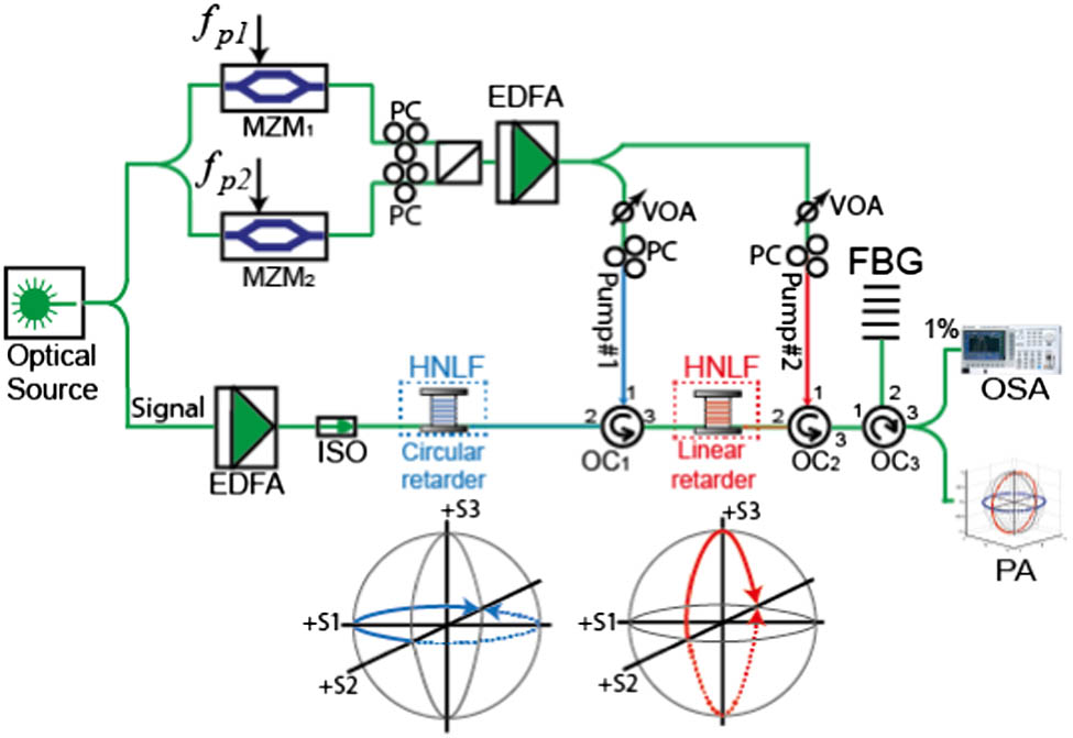
    Fig. 2. Block diagram of a nonlinear all-optical polarization controller made of one circular retarder plus one linear retarder. HNLF, highly nonlinear fiber; OC, optical circulator; ISO, isolator; VOA, variable optical attenuator; PC, polarization controller; FBG, fiber Bragg grating; OSA, optical spectrum analyzer; PA, polarization analyzer.
    Experimental results for a 0.16 mW input signal with linear polarization at 45º (Jones vector [1/2(1,1)]T). (a) (Left) Retardance induced as a function of pump power for the circular retarder: experiment (solid orange) and theory (dotted orange); (right) evolution of the signal degree of polarization (DOP) for the circular retarder as a function of pump power. (b) Poincaré sphere representation of the evolution of the output signal polarization over a circular retarder for an input signal. (c) Rotation of the signal SOP induced by the Brillouin-based circular and linear retarders.
    Fig. 3. Experimental results for a 0.16 mW input signal with linear polarization at 45º (Jones vector [1/2(1,1)]T). (a) (Left) Retardance induced as a function of pump power for the circular retarder: experiment (solid orange) and theory (dotted orange); (right) evolution of the signal degree of polarization (DOP) for the circular retarder as a function of pump power. (b) Poincaré sphere representation of the evolution of the output signal polarization over a circular retarder for an input signal. (c) Rotation of the signal SOP induced by the Brillouin-based circular and linear retarders.
    (a) (Left) Retardance induced as a function of pump power for the circular (blue solid) and linear (red solid) retarders for input signal with linear SOP at 45º (Jones vector [1/2(1,1)]T). (Right) Variation of the output signal power versus pump power. (b) Sphere’s rotation angle for input signal with ellipticity of ±0.5 (Jones vector [1/2(1,ejπ4)]T, [1/2(1,e−jπ4)]T). (c) Control of the retardance bandwidth; (blue) single pump configuration; (red) multitone pump configuration. (d) Comparison of the change of the noise figure for the proposed method (blue) and polarization pulling (orange).
    Fig. 4. (a) (Left) Retardance induced as a function of pump power for the circular (blue solid) and linear (red solid) retarders for input signal with linear SOP at 45º (Jones vector [1/2(1,1)]T). (Right) Variation of the output signal power versus pump power. (b) Sphere’s rotation angle for input signal with ellipticity of ±0.5 (Jones vector [1/2(1,ejπ4)]T, [1/2(1,ejπ4)]T). (c) Control of the retardance bandwidth; (blue) single pump configuration; (red) multitone pump configuration. (d) Comparison of the change of the noise figure for the proposed method (blue) and polarization pulling (orange).
    Retardance versus pump power for a Brillouin circular retarder for signals of 0.63 mW (dotted black), 0.16 mW (dotted red), 0.08 mW (dotted green), and 0.04 mW (dotted blue).
    Fig. 5. Retardance versus pump power for a Brillouin circular retarder for signals of 0.63 mW (dotted black), 0.16 mW (dotted red), 0.08 mW (dotted green), and 0.04 mW (dotted blue).
    Variation of the insertion loss of the polarization controller as a function of pump power for signals with different input power at the HNLF.
    Fig. 6. Variation of the insertion loss of the polarization controller as a function of pump power for signals with different input power at the HNLF.
    Temporal stability of the signal SOP at the output of the polarization controller. (a) Stokes parameters of the signal output with linear SOP at 135° as a function of time: S1 (blue solid curve), S2 (red solid curve), and S3 (yellow solid curve). Stokes parameters are normalized to S0. (b) (Red) signal SOP without SBS; (blue) signal SOP with SBS polarization conversion.
    Fig. 7. Temporal stability of the signal SOP at the output of the polarization controller. (a) Stokes parameters of the signal output with linear SOP at 135° as a function of time: S1 (blue solid curve), S2 (red solid curve), and S3 (yellow solid curve). Stokes parameters are normalized to S0. (b) (Red) signal SOP without SBS; (blue) signal SOP with SBS polarization conversion.
    Block diagram of a nonlinear all-optical polarization controller used to measure noise. HNLF, highly nonlinear fiber; OC, optical circulator; ISO, isolator; VOA, variable optical attenuator; FBG, fiber Bragg grating; OSA, optical spectrum analyzer; PA, polarization analyzer; ES, electrical spectrum analyzer; VNA, vector network analyzer.
    Fig. 8. Block diagram of a nonlinear all-optical polarization controller used to measure noise. HNLF, highly nonlinear fiber; OC, optical circulator; ISO, isolator; VOA, variable optical attenuator; FBG, fiber Bragg grating; OSA, optical spectrum analyzer; PA, polarization analyzer; ES, electrical spectrum analyzer; VNA, vector network analyzer.
    Diego Samaniego, Borja Vidal. Brillouin wavelength-selective all-optical polarization conversion[J]. Photonics Research, 2020, 8(4): 440
    Download Citation