
Jie Qiu, Liang Hao, Lihua Cao, Shiyang Zou. Collective stimulated Brillouin scattering modes of two crossing laser beams with shared scattered wave[J]. Matter and Radiation at Extremes, 2021, 6(6): 065903
- Matter and Radiation at Extremes
- Vol. 6, Issue 6, 065903 (2021)
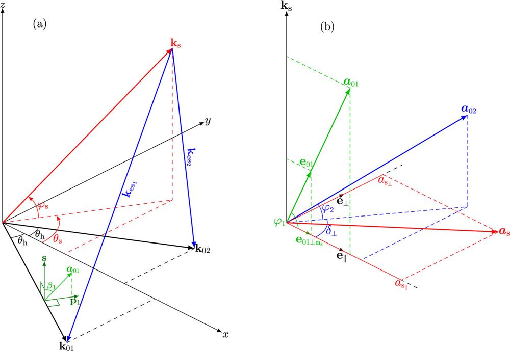
Fig. 1. (a) Geometry of collective SL modes for two overlapped beams. (For generality, a nonzero wavelength difference of these two beams is assumed.) In the presented coordinate system, the xy plane is chosen to be the (k 01, k 02) plane with the x axis along the bisector of k 01 and k 02 and the z axis along k 01 × k 02. Beam I or beam II is said to be s-polarized when ±a α is along the s (z -axis) direction and to be p-polarized when ±a α ∥p α is located in the xy plane. Other linear polarization states of beam I or II are described by the polarization angle 90° ≥ β α ≥ −90°, which is the angle from s to ±a α . (b) Relative orientation between the polarization directions of the two laser beams and the scattered light, where a k s (the polarization plane of the scattered light), and the angle between a α and this polarization plane is φ α . On this polarization plane, e ∥ is defined as the unit vector along the projection of a e ⊥ is a unit vector perpendicular to e ∥, and the angle between the projection of a a δ ⊥.
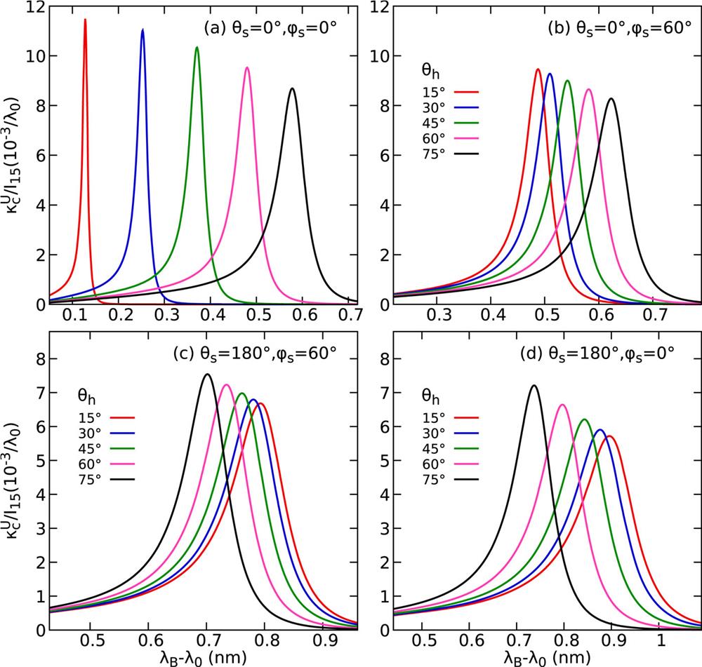
Fig. 2. κ c U / I 15 λ B − λ 0 for SL modes of two overlapping beams with the same intensity (I 01 = I 02 and I 15 ≡ I 01/1015 W/cm2) and the same vacuum wavelength (λ 0 = 351 nm) at different crossing angles for (a) θ s = 0°, φ s = 0°, (b) θ s = 0°, φ s = 60°, (c) θ s = 180°, φ s = 60°, and (d) θ s = 180°, φ s = 0°. The plasma condition n e = 0.06 n c, T e = 2.8 keV, T e/T i = 3.5, and zero flow velocity in a He plasma is taken.
Fig. 3. Upper and lower bounds of κ c / κ c U β 1 and β 2 are varied at each out-of-plane angle φ s. Two crossing laser beams with the same wavelength are assumed.
Fig. 4. κ c / κ c U φ s for SL modes of two beams with (a) and (b) θ h = 30° and (c) and (d) θ h = 60°.
Fig. 5. Achievable κ cl amp/I 15w b vs φ ̃ s β 1 = β 2 = 0, (b) β 1 = −β 2 = 45°, and (c) β 1 = β 2 = 90°, where φ ̃ s k 01 and k 02 (x direction) to n s, is equal to φ s for SL modes with θ s = 0, and is equal to φ s ± 180° for SL modes with θ s = 180°. The condition λ 0 = 351 nm, n e = 0.06 n c, T e = 2.5 keV, T e/T i = 3.5, and zero flow velocity for He plasma is taken.
Fig. 6. Possible directions of k s for SL modes of two crossing beams with different wavelength differences for beam crossing angles (a) θ h = 30° and (b) θ h = 60°. The (k 01, k 02) plane corresponding to φ s = 0 is indicated by the dashed curve, on which θ s = 0 as marked by the black circle corresponds to the bisector direction of k 01 and k 02, and θ s = θ h as marked by the black diamond corresponds to the direction of k 02. The indicated angle α ⊥ from the (k 01, k 02) plane to the (k s, k 02) plane can be used to denote different SL modes for specified Δλ 0 and θ h. The example of a He plasma with conditions λ 01 = 351 nm, n e = 0.06 n c, T e = 2.8 keV, T e/T i = 3.5, and zero flow velocity is taken.
Fig. 7. κ c U λ B − λ 01 for SL modes of two crossing beams with different wavelength differences and crossing angles. The contributions of beams I and II are shown by dashed and dotted curves, respectively, for the example of α ⊥ = 180° in (b). The example of a He plasma with conditions λ 01 = 351 nm, n e = 0.06 n c, T e = 2.8 keV, T e/T i = 3.5, and zero flow velocity is taken.
Fig. 8. Maps of κ cl amp/w bI 15 vs the direction of k s for SL modes of two crossing beams with different combinations of β 1 and β 2 at (a)–(c) θ h = 30° and (d)–(f) θ h = 60°. The direction of view is taken along − y ̂ k s loop for Δλ 0 = 0 appear as a unit circle on the maps. For θ h = 30°, the k s loops corresponding to Δλ 0 equal to 0, 0.2, 0.3, and 0.4 nm, which encircle the direction of k 02 (marked by the black diamonds), are shown by the cyan curves, while for θ h = 60°, the k s loops corresponding to Δλ 0 equal to 0, 0.2, 0.4, and 0.6 nm are displayed. The example of a He plasma with conditions λ 01 = 351 nm, n e = 0.06 n c, T e = 2.8 keV, T e/T i = 3.5, and zero flow velocity is taken.


Set citation alerts for the article
Please enter your email address

© Copyright 2018-2021 | Chinese Laser Press. All Rights Reserved 沪ICP备15018463号-20