• Matter and Radiation at Extremes
  • Vol. 6, Issue 6, 065903 (2021)
Jie Qiu1, Liang Hao1、a), Lihua Cao1、2, and Shiyang Zou1
Author Affiliations
  • 1Institute of Applied Physics and Computational Mathematics, Beijing 100094, China
  • 2HEDPS, Center for Applied Physics and Technology, Peking University, Beijing 100871, China
  • show less
    DOI: 10.1063/5.0062902 Cite this Article
    Jie Qiu, Liang Hao, Lihua Cao, Shiyang Zou. Collective stimulated Brillouin scattering modes of two crossing laser beams with shared scattered wave[J]. Matter and Radiation at Extremes, 2021, 6(6): 065903 Copy Citation Text show less

    Abstract

    In inertial confinement fusion (ICF), overlapping of laser beams is common. Owing to the effective high laser intensity of the overlapped beams, the collective mode of stimulated Brillouin scattering (SBS) with a shared scattered light wave is potentially important. In this work, an exact analytic solution for the convective gain coefficient of the collective SBS modes with shared scattered wave is presented for two overlapped beams based on a linear kinetic model. The effects of the crossing angle, polarization states, and finite beam overlapping volume of the two laser beams on the shared light modes are analyzed for cases with zero and nonzero wavelength difference between the two beams. It is found that all these factors have a significant influence on the shared light modes of SBS. Furthermore, the out-of-plane modes, in which the wavevectors of daughter waves lie in different planes from the two overlapped beams, are found to be important for certain polarization states and especially for obtuse crossing angles. In particular, adjusting the polarization directions of the two beams to be orthogonal to each other or tuning the wavelength difference to a sufficiently large value (of the order of nanometers) are found to be effective methods to suppress the shared light modes of SBS. This work will be helpful for comprehending and suppressing collective SBS with shared scattered waves in ICF experiments.

    I. INTRODUCTION

    In inertial confinement fusion (ICF), owing to the limited energy of a single laser beam, a large number of beams are needed to deliver the megajoule laser energy to the target required for both indirect-drive and direct-drive schemes.1–3 The ubiquitous overlapping of laser beams leads to complex multibeam laser–plasma interaction (LPI) instabilities, including crossed-beam energy transfer (CBET) between different beams,4–8 seeded multibeam instability due to seeds generated elsewhere in the plasma1 and by glint,9 and collective instability with shared daughter waves.3,10,11 Among the various LPI instabilities in ICF, stimulated Brillouin scattering (SBS) and stimulated Raman scattering (SRS) instabilities are of primary concern, since they can scatter significant amounts of light, leading to a great energy loss from the incident lasers as well as degradation of the irradiation symmetry.12–17 The collective modes with common daughter waves deserve particular attention owing to their great temporal growth rate and convective gain, which scale up with the number of pump beams.18–20 Experimentally, collective SRS and SBS result in significant scattered light losses in novel directions,19–21 which can be located far from the apertures of the beams where diagnostics are usually set up12,22 and are hence quite hard to detect. Understanding these processes is essential for better identifying, modeling, and diagnosing multibeam SRS or SBS processes and is helpful to optimize ICF implosions.

    The collective SRS or SBS processes include shared plasma (SP) wave modes and shared light (SL) wave modes, depending on whether the shared daughter wave is a common Langmuir/ion acoustic wave or a common scattered wave. Previous theoretical studies of the homogeneous temporal growth rate for collective SP and SL modes of multiple beams have been conducted using a fluid description.23–25 In addition, some two-dimensional (2D) particle-in-cell simulations have verified the importance of in-plane collective SRS modes of two overlapped beams,25,26 where the wavevectors of daughter waves lie in the plane of incidence of two overlapped beams. The SP modes of collective SBS in the spatial convective regime, which is typical of practical ICF conditions,27–29 have recently been studied, and it has been found that the out-of-plane modes can be quite important for some polarization states of the laser beams.30 In the present work, the SL modes of collective SBS in the convective regime are studied, and the impacts of the crossing angle, polarization states, and finite beam overlapping volume of the two laser beams on SL modes of SBS are investigated systematically for both zero and nonzero wavelength differences between the two pump beams. Compared with the SP modes, the SL modes are found to be much more sensitive to the polarization states and wavelength difference. Nevertheless, the out-of-plane modes can still be quite important for some polarization states and beam crossing angles. The results of this work should be helpful in comprehending and estimating the importance of collective SBS with shared scattered wave in ICF experiments.

    The remainder of the paper is organized as follows. In Sec. II, the theoretical model for SL modes is presented, where an analytic solution for the convective gain coefficient is given. In Sec. III, the impacts of the crossing angle, polarization states, and finite beam overlapping volume of the two laser beams on the scattered wavelength and spatial amplification of the collective SBS modes with shared scattered wave are investigated for both zero and nonzero wavelength differences between the pump lasers, and the importance of out-of-plane modes relative to in-plane modes is discussed. In Sec. IV, the conclusions are given, together with some discussions.

    II. THEORETICAL MODEL FOR SL MODES OF TWO CROSSING BEAMS

    The SL modes of two crossing beams incorporate five coupled waves: the two pump light waves and one common scattered light wave, as well as two plasma waves corresponding to the coupling between each pump light and the common scattered light. The phase matching conditions can be written asω0α=ωs+ωesα,k0α=ks+kesα,where the ωi with subscripts i = 0α, esα, and s (α = 1, 2) are the wave frequencies of laser beam α, plasma wave α, and the common scattered wave, respectively, and ki with i = 0α, esα, and s are the corresponding wavevectors. The geometry of the collective SL modes for two overlapped beams with crossing angle 2θh is shown in Fig. 1(a), where the xy plane is defined as the (k01, k02) plane with the x direction along the bisector of k01 and k02. The direction of the wavevector ks for the scattered wave can be specified by (θs, φs), where the out-of-plane angle −90° ≤ φs ≤ 90° is the altitude of ks measured from the xy plane, and the azimuthal angle −180° ≤ θs ≤ 180° is the angle from the x axis to the orthogonal projection of ks onto the xy plane. The wavevector kesα for the plasma wave driven by beam α is determined by the matching condition kesα = k0αks, yieldingkes1=k012+ks22k01ks2k01sin12ϑ1,kes2=k022+ks22k02ks2k02sin12ϑ2,where the approximate equality is applicable for collective SBS modes with a common scattered wave since ksk01k02 is taken for this approximation. ϑ1 and ϑ2 are the scattering angles of beams I and II and are defined bycosϑ1=k01ksk01ks=cosφscos(θs+θh),cosϑ2=k02ksk02ks=cosφscos(θsθh).

    (a) Geometry of collective SL modes for two overlapped beams. (For generality, a nonzero wavelength difference of these two beams is assumed.) In the presented coordinate system, the xy plane is chosen to be the (k01, k02) plane with the x axis along the bisector of k01 and k02 and the z axis along k01 × k02. Beam I or beam II is said to be s-polarized when ±a0α is along the s (z-axis) direction and to be p-polarized when ±a0α∥pα is located in the xy plane. Other linear polarization states of beam I or II are described by the polarization angle 90° ≥ βα ≥ −90°, which is the angle from s to ±a0α. (b) Relative orientation between the polarization directions of the two laser beams and the scattered light, where as is confined within the plane perpendicular to ks (the polarization plane of the scattered light), and the angle between a0α and this polarization plane is φα. On this polarization plane, e∥ is defined as the unit vector along the projection of a01, e⊥ is a unit vector perpendicular to e∥, and the angle between the projection of a01 and a02 is δ⊥.

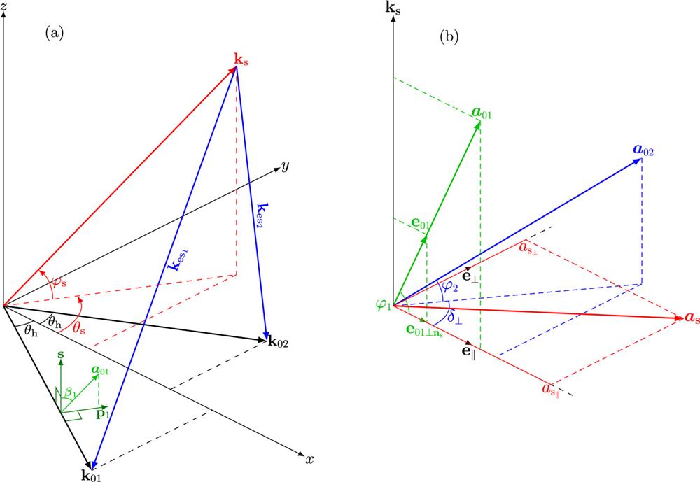
    Figure 1.(a) Geometry of collective SL modes for two overlapped beams. (For generality, a nonzero wavelength difference of these two beams is assumed.) In the presented coordinate system, the xy plane is chosen to be the (k01, k02) plane with the x axis along the bisector of k01 and k02 and the z axis along k01 × k02. Beam I or beam II is said to be s-polarized when ±a0α is along the s (z-axis) direction and to be p-polarized when ±a0αpα is located in the xy plane. Other linear polarization states of beam I or II are described by the polarization angle 90° ≥ βα ≥ −90°, which is the angle from s to ±a0α. (b) Relative orientation between the polarization directions of the two laser beams and the scattered light, where as is confined within the plane perpendicular to ks (the polarization plane of the scattered light), and the angle between a0α and this polarization plane is φα. On this polarization plane, e is defined as the unit vector along the projection of a01, e is a unit vector perpendicular to e, and the angle between the projection of a01 and a02 is δ.

    For most practical cases in ICF, both SRS and SBS are spatial problems,27,31,32 for which the convective amplification properties are of great importance. To study the convective amplification of the SL modes, the envelope approximation for the five coupled waves can be adopted. In the strong-damping regime, the equations for the complex vector amplitudes of the laser beams (a0α) and the common scattered wave (as), and for the complex amplitude of the density perturbation of plasma waves (δnesα) can be written as30,31δnesαn0=γpmαkesα2c22ωpe2a0αas*andksas=jωpe24c2α=1,2δnesα*n0a0αe0αns,where aieAi/mec is the normalization of the magnetic vector potential A, e is the electron charge, me is the electron mass, n0 is the unperturbed electron density, and c is the speed of light in vacuum. e0αnsns×(e0α×ns)=e0α(e0αns)ns is the projection of e0αa0α/a0α onto the plane perpendicular to nsks/ks, which arises because only this component of a0α can excite the electromagnetic component (perpendicular to ns) of the scattered wave. γpmα is the ponderomotive response function33 for plasma wave α, defined asγpm(ωes,kes)=(1+χI)χe1+χI+χe,where χI(ωes, kes) = Σβχiβ(ωes, kes) and χe(ωes, kes) are the ion susceptibility (summed over ion species β) and electron susceptibility,34 respectively. In this paper, for simplicity, the flow velocity is assumed to be zero for all species. Nevertheless, if species β were to flow with velocity uβ, then this nonzero flow velocity could easily be considered by replacing ωes in χiβ(ωes, kes) with ωeskes · uβ.35

    As illustrated in Fig. 1(b), the projections of the polarization directions e01 and e02 onto the plane perpendicular to ks can be different in direction, and then, according to Eq. (6), the direction of as depends on the competition between the drives by beams I and II. Defining e as the unit vector parallel to e01ns, and ens × e as the unit vector perpendicular to e and ns, as shown in Fig. 1(b), and writing as=ase+ase, Eqs. (5) and (6) can be written asδnes1n0=γpm1kes12c22ωpe2a01ascosφ1,δnes2n0=γpm2kes22c22ωpe2a02cosφ2(ascosδ+assinδ)andksas=jωpe24c2n0(δnes1a01cosφ1+δnes2a02cosφ2cosδ),ksas=jωpe24c2δnes2n0a02cosφ2sinδ,where φα is the angle between e0αns and e0α, which satisfies cos φα = |e0α × ns|, and δ is the angle between e01ns and e02ns, which satisfiessinδ=ns(e01×e02)cosφ1cosφ2.Inserting Eqs. (8) and (9) into Eqs. (10) and (11), equations for as and as can be obtained asηas=κ1as+κ2cosδ(ascosδ+assinδ),ηas=κ2sinδ(ascosδ+assinδ),where the coordinate η is along the direction of ks, and the single-beam gain coefficients are κ1Im[γpm1]kes12|a01|2cos2φ1/8ks and κ2Im[γpm2]kes22|a02|2cos2φ2/8ks. The gain coefficient κc of the common scattered wave can be obtained from Eqs. (13) and (14) by taking the solution form as,aseκcη, yieldingκc2κc(κ1+κ2)+κ1κ2sin2δ=0.Usually, there are two solutions for κc, with the larger one satisfying max[κ1, κ2] ≤ κcκ1 + κ2 and the smaller one satisfying 0 ≤ κc ≤ min[κ1, κ2]. The polarization directions of as corresponding to these two modes are orthogonal to each other and are determined byasas=κ2cosδsinδκcκ2sin2δ.The mode with larger κc will dominate the convective amplification of the scattered wave, except when the polarization direction of the seed for as is exactly along the polarization direction of the mode with smaller κc. Therefore, it is the SL mode with larger κc that is mainly discussed in this work.

    III. COLLECTIVE SBS MODES WITH SHARED SCATTERED WAVE FOR TWO OVERLAPPED BEAMS

    In this section, we investigate the impacts of crossing angle, polarization states, and the finite overlapping volume of the two laser beams on collective SBS modes with shared scattered wave for both zero and nonzero wavelength differences between the two pump beams.

    Assuming zero flow velocity, the ion acoustic waves satisfy the dispersion relation ωaα=kaαcs, where cs is the ion acoustic velocity. (Note that in the context of SBS, the subscript “a” is used to denote quantities related to ion acoustic waves, which corresponds to the symbol “es” for plasma waves in Sec. II.) Then, from the matching conditionωs=ω01ωa1=ω02ωa2,we obtain the requirementΔω0ω01ω02=ωa1ωa2=cs(ka1ka2).Thus, for two laser beams of the same wavelength, i.e., Δω0 = 0, it is required that ka1=ka2, leading to θs = 0° or θs = 180°, while for Δω0 ≠ 0, the possible directions of ks are determined by Eq. (18) in combination with Eqs. (3) and (4), which is much more complicated. In the following, we discuss these two cases separately.

    A. SL modes for two beams with the same wavelength

    For the SL modes of collective SBS, since ka1=ka2 when the two pump beams have the same wavelength, ks is located on the bisecting plane between k01 and k02 (the xz plane in Fig. 1), and the ponderomotive response γpm1=γpm2 owing to the symmetric matching condition. Thus, the single-beam gain coefficient κα=(Im[γpm]ka2/8ks)|a0α|2cos2φα. Considering two beams with the same intensity, the gain coefficient for the SL mode has the upper limit κcκ1+κ2κcU(Im[γpm]ka2/4ks)|a0|2. According to Eq. (15), κc/κcU is the larger root of the following equation:2κcκcU22cos2φ1+cos2φ2κcκcU+(cosφ1cosφ2sinδ)2=0,where the factors cos φ1, cos φ2 and sin δ depend solely on the geometry (θh, φs, θs = 0° or 180°) of the SL mode and the polarization states of the laser beams, which are denoted by the polarization angle βα (−90° < βα ≤ 90°), as shown in Fig. 1. Therefore, κc/κcU is determined completely by the beam crossing angle θh, the out-of-plane angle φs, and the polarization angles β1 and β2, while the dependence of κcU on the scattered wavelength is reflected in the gain spectrum of κcU.

    For a typical plasma condition at the laser entrance hole of a He plasma,36κcU is shown in Fig. 2, in which the gain coefficient is normalized by I15 = I01[W/cm2]/1015. For θs = 0° and −90° < φs < 90°, where ks is in the quadrants x > 0, the scattered wavelength increases with increasing θh, while the peak value of κcU decreases with increasing θh. This is because the term ka2Im[γpm] in κcU peaks at ωakacs (λBλ0ωaka), with its peak value decreasing with increasing ka,30 and ka = 2k0 sin[arccos( cos φs cos θh)/2] for θs = 0° [obtained from Eqs. (3) and (4)] increases with increasing θh. For θs = 180° and −90° < φs < 90°, where ks is in the quadrants x < 0, the scattered wavelength decreases with increasing θh, while the peak value of κcU increases with increasing θh. This is because ka = 2k0 cos[arccos(cos φs cos θh)/2] for θs = 180° decreases with increasing θh. Besides, ka increases as the angle between ks and x^ increases from zero to 180°, which corresponds to φs varying from 0 to 90° for θs = 0° and then from 90° to 0 for θs = 180°, as shown in Fig. 1. Consequently, the scattered wavelength increases while the peak gain value decreases as the angle between ks and x^ increases from 0° through 90° to 180°, as shown in Fig. 2.

    κcU/I15 vs λB − λ0 for SL modes of two overlapping beams with the same intensity (I01 = I02 and I15 ≡ I01/1015 W/cm2) and the same vacuum wavelength (λ0 = 351 nm) at different crossing angles for (a) θs = 0°, φs = 0°, (b) θs = 0°, φs = 60°, (c) θs = 180°, φs = 60°, and (d) θs = 180°, φs = 0°. The plasma condition ne = 0.06 nc, Te = 2.8 keV, Te/Ti = 3.5, and zero flow velocity in a He plasma is taken.

    Figure 2.κcU/I15 vs λBλ0 for SL modes of two overlapping beams with the same intensity (I01 = I02 and I15I01/1015 W/cm2) and the same vacuum wavelength (λ0 = 351 nm) at different crossing angles for (a) θs = 0°, φs = 0°, (b) θs = 0°, φs = 60°, (c) θs = 180°, φs = 60°, and (d) θs = 180°, φs = 0°. The plasma condition ne = 0.06 nc, Te = 2.8 keV, Te/Ti = 3.5, and zero flow velocity in a He plasma is taken.

    The influence of polarization on κc of the SL modes can be evaluated through κc/κcU determined by Eq. (19). Owing to the symmetric relation κc/κcU|θs=180°,φs=κc/κcU|θs=0,φs, in the following discussion of the modification of κc by polarization states, we assume θs = 0. First, it is observed that the range of κc/κcU attainable by adjusting the polarization angles β1 and β2 depends on the out-of-plane angle φs. In particular, κc/κcU=1 can be attained only for in-plane scattering (φs = 0) when both beams are s-polarized (β1 = β2 = 0), while κc/κcU<1 for all combinations of β1 and β2 when φs ≠ 0. The upper and lower bounds of the range of κc/κcU at each φs can be obtained analytically, as given by Eqs. (A1)(A4) in Appendix A. Figure 3 shows the variation of the range of κc/κcU with φs for different crossing angles. As can be seen, the range of variation of κc/κcU is quite broad, especially for large obtuse crossing angles, indicating the significant role played by the polarization in the SL modes. As a result, the SL mode at some out-of-plane angle φs can be enhanced or reduced effectively by adjusting β1 and β2. For a specified φs, the upper bound of κc/κcU depends on the best achievable alignment between the polarization directions of the two laser beams and the common scattered wave. Complete alignment among these three waves is only possible for in-plane scattering (φs = 0), where the polarization direction perpendicular to k01 and k02 is also orthogonal to ks. For out-of-plane scattering, the best achievable polarization alignment decreases with increasing out-of-plane angle, making κc/κcU drop with φs. Notice that for an acute crossing angle where θh < 45°, at small φs, for the best achievable polarization alignment, the SL modes with as along the direction of y^×ns have larger gain coefficient, while at large φs, the SL modes with as along the direction of y^ have larger gain coefficient, and the best alignment occurs when both laser beams are p-polarized, and their alignment with as along y^ is independent of φs, leading to a constant κc/κcU. This results in a curvature inflection of the upper bound of κc/κcU, as shown in Fig. 3.

    Upper and lower bounds of κc/κcU when β1 and β2 are varied at each out-of-plane angle φs. Two crossing laser beams with the same wavelength are assumed.

    Figure 3.Upper and lower bounds of κc/κcU when β1 and β2 are varied at each out-of-plane angle φs. Two crossing laser beams with the same wavelength are assumed.

    To see the relative importance of SL modes with different out-of-plane angles for specified polarization states, we consider the relation between κc/κcU and φs when β1 and β2 are specified. Several special cases can be identified:When both beams I and II are s-polarized (β1 = β2 = 0), it is found that κc/κcU=cos2φs. Consequently, for this polarization state, the in-plane SL mode is favored.When both beams are p-polarized (β1 = β2 = 90°), it is found for |sin φs| ≤ 1/tan θh that κc/κcUcos2θh over −90° < φs ≤ 90°, where as is along the y^ direction, and hence its alignment with the p-polarized laser beams is independent of the out-of-plane angle; otherwise, the orthogonal mode with as along the y^×ns direction has a larger gain coefficient, rendering κc/κcU=sin2θhsin2φs, more favorable for out-of-plane modes.When the polarization directions of the two pump beams are orthogonal (e01 · e02 = 0), it is found that as lies in the (e01, e02) plane, and the orthogonal drives of the two beams complement each other, making κc/κcU1/2 over −90° < φs ≤ 90°. Thus, κc is just the same as the gain coefficient of the single-beam side-scatter at the same scattering angle, for which the mode with ks perpendicular to e0α, and hence complete polarization alignment, is always allowed. The gain enhancement by sharing of the scattered wave vanishes for this polarization state, indicating that the SL mode can be effectively suppressed by tuning the polarization directions of the two pump beams to be orthogonal.

    For other combinations of β1 and β2, the typical variation of κc/κcU with φs is shown in Fig. 4. Generally, there exists one most favored mode corresponding to the maximum value of κc/κcU at some out-of-plane angle φsM. Further analysis shows that this maximum value is completely determined by the polarization alignment between the two pump beams,maxφsκcκcU=12(1+|cosδpol|),wherecosδpole01e02=cos2θhcos(β1β2)+sin2θhcos(β1+β2).The detailed derivation is given in Appendix B. This maximum value is attained when the polarization direction of as is along the bisector of the acute angles between e01 and e02 (i.e., along e01 + e02 for  cos δpol > 0 and e01e02 for cos δpol < 0). This condition, together with the requirement asks, then givestanφsM=tan[(β1β2)/2]sinθh,cosδpol>0,sinθhtan[(β1β2)/2],cosδpol<0.Therefore, the out-of-plane angle |φsM| of the most favored SL mode is largely determined by β1β2, which characterizes the overall deviation from s-polarization of beams I and II. Typically, there is a jump in φsM at cos δpol = 0, where the sign of φsM becomes opposite. Before this jump, |φsM| increases with increasing |β1β2|, and after it, |φsM| decreases with increasing |β1β2|. For an acute crossing angle with θh < 45°, the upper limit of |φsM| is arctan(sinθh/cos2θh), corresponding to 15.5° and 35.3° for θh = 15° and 30°, respectively, while for an obtuse crossing angle with θh > 45°, |φsM| can reach 90° when β1 = β2 ≥ 90° − arccos(1/ tan2θh)/2. Thus, for small acute crossing angles, the out-of-plane modes with relatively small out-of-plane angles can be favored for some polarization states, while for large obtuse crossing angles, the large-angle out-of-plane SL modes can also be favored.

    κc/κcU vs φs for SL modes of two beams with (a) and (b) θh = 30° and (c) and (d) θh = 60°.

    Figure 4.κc/κcU vs φs for SL modes of two beams with (a) and (b) θh = 30° and (c) and (d) θh = 60°.

    In practice, the overlapping volume of the laser beam is finite, limiting the amplification length lamp (along the ns direction) of the SL modes. If it is assumed that the laser width is wb, then, to enclose the amplification length inside the overlapping volume, it is required that lamp|nsk01|wb and lamp|nsk02|wb, where nsk0α is the projection of ns onto the plane perpendicular to the laser propagation direction k0α. This gives the greatest amplification length lamp=wb/1cos2φscos2θh for two beams at the same wavelength. It can be seen that lamp decreases with increasing out-of-plane angle; however, the rate of decrease drops with increasing crossing angle, corresponding to a decrease of about 74%, 50%, 29%, 13%, and 3% when φs increases from 0° to 90°, for θh at 15°, 30°, 45°, 60° and 75°, respectively. Considering this effect, the achievable gain κclamp/wb of the SL modes with different out-of-plane angles is shown in Fig. 5 for three polarization combinations β1 = β2 = 0, β1 = −β2 = 45°, and β1 = β2 = 90°, where the value of κc at the peak wavelength is used. For small crossing angle θh = 15°, the gains of the in-plane modes are always larger than those of the out-of-plane modes, irrespective of the beam polarization, owing to the rapidly falling amplification length with increasing φs. For larger crossing angles, however, the relative importance of the out-of-plane modes with respect to the in-plane modes depends on the polarization states of the laser beams. Especially for large obtuse crossing angles, the gains of the out-of-plane SL modes can significantly exceed those of the in-plane modes for certain polarization states, even when the effects of finite beam overlapping volume have been taken into account.

    Achievable κclamp/I15wb vs φ̃s for (a) β1 = β2 = 0, (b) β1 = −β2 = 45°, and (c) β1 = β2 = 90°, where φ̃s as the angle from the bisector of k01 and k02 (x direction) to ns, is equal to φs for SL modes with θs = 0, and is equal to φs ± 180° for SL modes with θs = 180°. The condition λ0 = 351 nm, ne = 0.06 nc, Te = 2.5 keV, Te/Ti = 3.5, and zero flow velocity for He plasma is taken.

    Figure 5.Achievable κclamp/I15wb vs φ̃s for (a) β1 = β2 = 0, (b) β1 = −β2 = 45°, and (c) β1 = β2 = 90°, where φ̃s as the angle from the bisector of k01 and k02 (x direction) to ns, is equal to φs for SL modes with θs = 0, and is equal to φs ± 180° for SL modes with θs = 180°. The condition λ0 = 351 nm, ne = 0.06 nc, Te = 2.5 keV, Te/Ti = 3.5, and zero flow velocity for He plasma is taken.

    B. SL modes for two beams with nonzero wavelength difference

    For two beams with nonzero wavelength difference, on substituting the expression (3) for kes1=ka1 and kes2=ka2 into the matching requirement (18) for the SL mode, it is found thatΔω04k01cs=cosϑ1+ϑ24sinϑ1ϑ24,where the scattering angles ϑ1 for beam I and ϑ2 for beam II are functions of θh, θs, and φs. Without loss of generality, we designate the beam with shorter wavelength as beam I, and then Δω0 = ω01ω02 ≥ 0 and Δλ0=λ02λ01λ012Δω0/2πc0, where λ01 and λ02 are the vacuum wavelengths of beams I and II, respectively. Since the maximum value of the right-hand side of Eq. (23) as a function of θs and φs is 12sinθh located at θs = θh and φs = 0, it is required that Δω0 ≤ 2k01cs sin θh and hence Δλ02λ01cssinθh1ne/nc/c for the SL modes to exist. For given Δλ0, the possible directions of ks for the SL modes as obtained from Eq. (23) constitute a loop on the (θs, φs) sphere, as shown in Fig. 6. When Δλ0 = 0, the ks loop constitutes a great circle in the xz plane perpendicular to k01k02. With increasing Δλ0, the ks loop contracts to a smaller and smaller loop encircling the wavevector direction of the laser beam with longer wavelength (here the direction of k02 at θs = θh and φs = 0), until at the greatest allowed wavelength difference 2λ01cssinθh1ne/nc/c, the ks loop retracts to one point corresponding to the direction of k02. The contraction of the ks loop is more severe for a smaller beam crossing angle, for which the greatest allowed wavelength difference is smaller. By tuning the wavelength difference between the two pump beams greater than 2λ01cs1ne/nc/c, SL modes are diminished for any beam crossing angle. This provides an efficient way to suppress the SL modes of SBS.

    Possible directions of ks for SL modes of two crossing beams with different wavelength differences for beam crossing angles (a) θh = 30° and (b) θh = 60°. The (k01, k02) plane corresponding to φs = 0 is indicated by the dashed curve, on which θs = 0 as marked by the black circle corresponds to the bisector direction of k01 and k02, and θs = θh as marked by the black diamond corresponds to the direction of k02. The indicated angle α⊥ from the (k01, k02) plane to the (ks, k02) plane can be used to denote different SL modes for specified Δλ0 and θh. The example of a He plasma with conditions λ01 = 351 nm, ne = 0.06 nc, Te = 2.8 keV, Te/Ti = 3.5, and zero flow velocity is taken.

    Figure 6.Possible directions of ks for SL modes of two crossing beams with different wavelength differences for beam crossing angles (a) θh = 30° and (b) θh = 60°. The (k01, k02) plane corresponding to φs = 0 is indicated by the dashed curve, on which θs = 0 as marked by the black circle corresponds to the bisector direction of k01 and k02, and θs = θh as marked by the black diamond corresponds to the direction of k02. The indicated angle α from the (k01, k02) plane to the (ks, k02) plane can be used to denote different SL modes for specified Δλ0 and θh. The example of a He plasma with conditions λ01 = 351 nm, ne = 0.06 nc, Te = 2.8 keV, Te/Ti = 3.5, and zero flow velocity is taken.

    The ks loop can be parameterized by −180° < α ≤ 180°, the angle from (k01, k02) plane to (ks, k02) plane, where the in-plane SL modes correspond to α = 0 or 180°.44 One upper bound of κc for all possible polarization states is κcU=α=1,2Im[γpmα]kaα2|a0α|2/8ks. We can again can use κcU to characterize the dependence of κc on the scattered wavelength, as shown in Fig. 7 for SL modes of two laser beams with different wavelength differences. Since the system is symmetric with respect to reflection at the (k01, k02) plane, 0 ≤ α ≤ 180° is shown. In Fig. 7(b), the contributions of beams I and II to κcU are also displayed for α = 180°. Since ka2<ka1, the contribution of beam II has a greater peak value yet a narrower width compared with beam I. Hence, beam II with the longer wavelength contributes more to the peak of κcU, whereas beam I with the shorter wavelength contributes more to the wing of κcU. For each Δλ0, because the scattering angles ϑ1 and ϑ2 and hence ka1 and ka2 increase with increasing α, the peak wavelength increases with increasing α, while the peak value of κcU decreases. Furthermore, with increasing Δλ0, the shortest peak wavelength of the SL mode with α = 0 increases, while the longest peak wavelength of the SL mode with α = 180° decreases, because of the contraction of the ks loop. This leads to a narrower wavelength range for the possible SL modes when the laser wavelength difference is enlarged. Also, it can be shown that the shortest peak wavelength of the SL mode with α = 0 increases with increasing θh, while the longest peak wavelength of the SL mode with α = 180° increases with increasing θh when θh<2arcsin(|Δω0|/4k0cs), and decreases with increasing θh for a larger beam crossing angle.

    κcU vs λB − λ01 for SL modes of two crossing beams with different wavelength differences and crossing angles. The contributions of beams I and II are shown by dashed and dotted curves, respectively, for the example of α⊥ = 180° in (b). The example of a He plasma with conditions λ01 = 351 nm, ne = 0.06 nc, Te = 2.8 keV, Te/Ti = 3.5, and zero flow velocity is taken.

    Figure 7.κcU vs λBλ01 for SL modes of two crossing beams with different wavelength differences and crossing angles. The contributions of beams I and II are shown by dashed and dotted curves, respectively, for the example of α = 180° in (b). The example of a He plasma with conditions λ01 = 351 nm, ne = 0.06 nc, Te = 2.8 keV, Te/Ti = 3.5, and zero flow velocity is taken.

    Taking into account the effects of the polarization states and the finite beam overlapping volume of the two laser beams, the achievable κclamp/wb can be calculated for an arbitrary allowed Δλ0, similar to the case for Δλ0 = 0. Combining the results for different Δλ0 and taking the value of κc at the peak wavelength, a map of κclamp/wb vs the direction of ks can be obtained, as shown in Fig. 8, where a view along the y^ direction (cf. Fig. 1) is taken. It is clear that the polarization states can significantly modify the gain of the SL modes. Especially for large beam crossing angles and relatively small Δλ0, for which the ks loop is relatively large, the out-of-plane SL modes with φs deviating from zero can be quite important, similar to the case with zero laser wavelength difference discussed above.

    Maps of κclamp/wbI15 vs the direction of ks for SL modes of two crossing beams with different combinations of β1 and β2 at (a)–(c) θh = 30° and (d)–(f) θh = 60°. The direction of view is taken along −ŷ, making the ks loop for Δλ0 = 0 appear as a unit circle on the maps. For θh = 30°, the ks loops corresponding to Δλ0 equal to 0, 0.2, 0.3, and 0.4 nm, which encircle the direction of k02 (marked by the black diamonds), are shown by the cyan curves, while for θh = 60°, the ks loops corresponding to Δλ0 equal to 0, 0.2, 0.4, and 0.6 nm are displayed. The example of a He plasma with conditions λ01 = 351 nm, ne = 0.06 nc, Te = 2.8 keV, Te/Ti = 3.5, and zero flow velocity is taken.

    Figure 8.Maps of κclamp/wbI15 vs the direction of ks for SL modes of two crossing beams with different combinations of β1 and β2 at (a)–(c) θh = 30° and (d)–(f) θh = 60°. The direction of view is taken along ŷ, making the ks loop for Δλ0 = 0 appear as a unit circle on the maps. For θh = 30°, the ks loops corresponding to Δλ0 equal to 0, 0.2, 0.3, and 0.4 nm, which encircle the direction of k02 (marked by the black diamonds), are shown by the cyan curves, while for θh = 60°, the ks loops corresponding to Δλ0 equal to 0, 0.2, 0.4, and 0.6 nm are displayed. The example of a He plasma with conditions λ01 = 351 nm, ne = 0.06 nc, Te = 2.8 keV, Te/Ti = 3.5, and zero flow velocity is taken.

    IV. DISCUSSION AND SUMMARY

    In summary, based on a linear kinetic model, an analytic convective solution has been derived for the SL modes of two overlapped laser beams. The effects of crossing angle, polarization states, and the finite overlapping volume of the two beams on the collective SBS modes with shared scattered waves have been discussed in detail for both zero and nonzero wavelength differences between the two laser beams. When the two beams are of the same wavelength, the wavevectors of the shared scattered waves lie on a circle in the bisecting plane between the wavevectors of the two laser beams. The wavelength of the scattered waves varies with the beam crossing angle and the out-of-plane angle of the SL modes. The gain coefficients of the SL modes, on the other hand, are also subject to the polarization states of the laser beams. When the two laser beams are both s-polarized, the gain coefficient of the SL mode is twice the gain coefficient of a single beam, while when the polarization directions of the two beams are orthogonal to each other, the gain coefficient of the collective SBS modes becomes the same as the single-beam side-scatter with the same scattering angle. Furthermore, for some polarization states and especially for obtuse crossing angles, the out-of-plane SL modes can become more important than the in-plane modes. With increasing wavelength difference between the two laser beams, the possible directions of the wavevectors of the common scattered wave contract toward the wavevector direction of the pump beam with longer wavelength. This changes the scattered wavelengths and the gain coefficients of the SL modes. Nevertheless, depending on the polarization state and the beam crossing angle, the out-of-plane modes can still be quite important. Finally, for sufficiently large vacuum wavelength difference Δλ0>2λ01cs1ne/nc/c, the SL modes of SBS no longer exist, which provides an efficient way to suppress the SL modes of SBS.

    In this work, uniform plasma conditions with zero flow velocity have been assumed for an illustrative analysis. A nonzero flow velocity effectively leads to an additional wavelength difference between the two laser beams, which can also be accounted for by our model. Furthermore, in ICF, various laser smoothing techniques, such as kinoform/random phase plate (KPP/RPP),37 smoothing by spectral dispersion (SSD),38 polarization smoothing (PS),39 and some new methods,40–42 are often used to suppress LPI. Consequently, the laser beam intensity distribution can be highly nonuniform with many high-intensity speckles, and the induced temporal/spatial incoherence of the laser beam introduces additional mismatching into SBS, leading to a modified ponderomotive response γpm.43 To obtain a precise gain by integrating the local gain coefficient, these two factors, along with the realistic overlapping pattern of the laser beams,20,32 should be properly taken into account in further simulations. The collective SL modes can have much higher gain coefficient than single-beam SBS, and consequently they can be amplified to a great magnitude over a short distance. Especially for practical inhomogeneous plasmas, when the resonance length is limited by the inhomogeneity of the flow velocity or temperature,5,32 the collective SL mode could dominate over the single-beam SBS mode. Finally, from a comparison with the collective SP modes investigated in Ref. 30, it is found that depending on the crossing angle, polarization states, and the wavelength difference between the two laser beams, either the SP or the SL mode can be more important. Simulations under realistic plasma and laser conditions are required to assess the importance of the SL modes, for which this work provides valuable theoretical references.

    ACKNOWLEDGMENTS

    Acknowledgment. This work was supported by the National Key R&D Program of China (Grant No. 2017YFA0403204), the Science Challenge Project (Grant No. TZ2016005), the National Natural Science Foundation of China (Grant Nos. 11 875 093 and 11 875 091), and the Project supported by CAEP Foundation (Grant No. CX20210040).

    APPENDIX A: ACHIEVABLE RANGE OF κc/κcU AT EACH φs BY ADJUSTING β1 AND β2 FOR TWO CROSSING BEAMS WITH SAME WAVELENGTH AND INTENSITY

    By analysis, it is found that both the upper and lower bounds of κc/κcU are attained at β1 = −β2, when the polarization states of beams I and II are symmetric with respect to the bisecting plane between k01 and k02. The upper bound ismaxβ1,2κcκcU=max[1cos2θhsin2φs,cos2θh],and the corresponding polarization angles areβ1=β2=arctan(tanφssinθh),|sinφs|<tanθh,±90°,otherwise.For the former case, as is along the direction of y^×ns, and for the latter case, as is along the direction of y^. The lower bound isminβ1,2κcκcU=(cosφscosθh)2cos2φs+(cosθh+sinθh|sinφs|)2and the corresponding polarization angles areβ1=β2=arctansgn(φs)cosφscosθh+sinθh|sinφs|,where sgn(·) is the sign function.

    APPENDIX B: MAXIMUM VALUE OF κc/κcU VS φs FOR TWO CROSSING BEAMS WITH SAME WAVELENGTH AND INTENSITY WHEN THEIR POLARIZATION STATES ARE GIVEN

    In this case, the polarization direction of beam α (α = 1, 2) along the unit vector e0α is given while the propagation direction ns of the scattered light is varied. To obtain maxφs[κc/κcU], it is much easier to express φ1, φ2 and δ in Eq. (19) in terms of the relative orientation between e01, e02, and ns. Without loss of generality, for now we assume the angle δpol between e01 and e02 is less than 90°, making cos δpol ≥ 0. (Since the unit polarization vectors can be chosen freely between ±e01 and ±e02, we can always ensure an acute angle between them.) Denoting the angle between ns and the (e01, e02) plane as θ, and the angle between the projection of ns onto this plane and the bisector of e01 and e02 as θ, we have sin φα = e0α · ns = cos θ cos(θ ± δpol/2) (α = 1, 2), and sin δ cos φ1 cos φ2 = (e01 × e02) · ns = sin δpol sin θ. [See Eq. (12).] Equation (19) can thus be written as2κcκcU2[2cos2θ(1+cos2θcosδpol)]2κcκcU+sin2δpolsin2θ=0.With the change in the direction of ns, both θ and θ change, and it is easy to see that the larger root of this quadratic equation increases with decreasing cos 2θ, and so maxθ[κc/κcU] is attained when cos 2θ = −1. At cos 2θ = −1, Eq. (B1) becomes2κcκcU2[1+cosδpol+sin2θ(1cosδpol)]2κcκcU+sin2δpolsin2θ=0.Since cos δpol ≥ 0 is assumed, it can be determined that the larger root for κc/κcU is (1 + cos δpol)/2. Since this maximum value is independent of θ, we have actually obtained maxθ,θ[κc/κcU]=maxφs[κc/κcU]=(1+|cosδpol|)/2. Furthermore, from Eq. (16), it can be found that for this maximum value, as is along e01 + e02, i.e., the bisector of acute angles between e01 and e02.

    References

    [1] I. V.Igumenshchev, D. H.Froula, D. H.Edgell, J.Zhang, R. W.Short, W.Seka, P.Michel, J. F.Myatt, D. T.Michel, A. V.Maximov, D. E.Hinkel, J. D.Moody. Multiple-beam laser-plasma interactions in inertial confinement fusion. Phys. Plasmas, 21, 055501(2014).

    [2] L.Divol, L.Yin, D.Hinkel, J.Kline, M.Rosen, J. D.Moody, R.Berger, O.Landen, J.Lindl, E.Dewald, J.Milovich, H.Rose, R. K.Kirkwood, E.Williams, S.Glenzer, P.Michel, B.Macgowan. A review of laser-plasma interaction physics of indirect-drive fusion. Plasma Phys. Controlled Fusion, 55, 103001(2013).

    [3] Y. J.Gu, S.Weber, V.Tikhonchuk, J.Limpouch, O.Klimo. Studies of laser-plasma interaction physics with low-density targets for direct-drive inertial confinement schemes. Matter Radiat. Extremes, 4, 045402(2019).

    [4] C. A.Thomas, P.Michel, B. J.MacGowan, S.Weber, S. W.Haan, L.Divol, J. D.Lindl, M. J.Edwards, L. J.Suter, S. H.Glenzer, S.Dixit, D. A.Callahan, E. A.Williams, J. D.Salmonson, D. E.Hinkel. Tuning the implosion symmetry of ICF targets via controlled crossed-beam energy transfer. Phys. Rev. Lett., 102, 025004(2009).

    [5] S.Dixit, S.Le Pape, S.Glenn, P.Michel, S. H.Glenzer, B. J.MacGowan, K.Widmann, R.Town, L. J.Suter, D.Hinkel, G. A.Kyrala, W. L.Kruer, D. K.Bradley, E. A.Williams, R. K.Kirkwood, J. L.Kline, N. B.Meezan, L.Divol, J.Lindl, D.Callahan. Symmetry tuning via controlled crossed-beam energy transfer on the National Ignition Facility. Phys. Plasmas, 17, 056305(2010).

    [6] M. J.Edwards, E. I.Moses, M. B.Schneider, J. D.Kilkenny, J. D.Moody, A.Nikroo, R. L.Berger, D. A.Callahan, K.Widmann, L. J.Atherton, C.Haynam, D. J.Strozzi, E. L.Dewald, E.Bond, R. K.Kirkwood, O.Jones, S. H.Glenzer, S.LePape, J. D.Lindl, S.Glenn, L. J.Suter, N.Izumi, L.Divol, C. A.Thomas, P.Michel, O. L.Landen, E. A.Williams, G. A.Kyrala, D. E.Hinkel, J. L.Kline, R. P. J.Town, D. K.Bradley, W. L.Kruer, B. J.MacGowan, S.Dixit, N. B.Meezan, A.Hamza, M. D.Rosen. Multistep redirection by cross-beam power transfer of ultrahigh-power lasers in a plasma. Nat. Phys., 8, 344-349(2012).

    [7] L.Hao, X. Y.Hu, J.Xiang, C. Y.Zheng, Z. J.Liu, B.Li. Study of crossed-beam energy transfer process with large crossing angle in three-dimension. Laser Part. Beams, 34, 270-275(2016).

    [8] W.Rozmus, V. V.Eliseev, V. T.Tikhonchuk, C. E.Capjack. Interaction of crossed laser beams with plasmas. Phys. Plasmas, 3, 2215-2217(1996).

    [9] L.Divol, A. L.Kritcher, J. S.Ross, J. D.Moody, P.Michel, J. E.Ralph, L. F.Berzak Hopkins, D.Turnbull, D. E.Hinkel. Multibeam seeded Brillouin sidescatter in inertial confinement fusion experiments. Phys. Rev. Lett., 114, 125001(2015).

    [10] B.Yaakobi, S. X.Hu, A. V.Maximov, J. F.Myatt, A. A.Solodov, W.Seka, R. W.Short, D. T.Michel, D. H.Froula. Experimental validation of the two-plasmon-decay common-wave process. Phys. Rev. Lett., 109, 155007(2012).

    [11] J. D.Moody, R. L.Berger, M.Hohenberger, E. L.Dewald, W. L.Kruer, O. S.Jones, P.Michel, J. L.Milovich, L.Divol, L. B.Hopkins. Multibeam stimulated Raman scattering in inertial confinement fusion conditions. Phys. Rev. Lett., 115, 055003(2015).

    [12] R. L.Berger, S. H.Glenzer, R. L.Kauffman, P.Amendt, J. D.Lindl, S. W.Haan, L. J.Suter, O. L.Landen, S. G.Glendinning. The physics basis for ignition using indirect-drive targets on the National Ignition Facility. Phys. Plasmas, 11, 339-491(2004).

    [13] D. S.Montgomery. Two decades of progress in understanding and control of laser plasma instabilities in indirect drive inertial fusion. Phys. Plasmas, 23, 055601(2016).

    [14] L.Hao, L. H.Cao, Z. J.Liu, C. Z.Xiao, X. T.He, Q. S.Feng, C.Ning, C. Y.Zheng. Interaction of parametric instabilities from 3ω and 2ω lasers in large-scale inhomogeneous plasmas. Nucl. Fusion, 60, 066012(2020).

    [15] C. Y.Zheng, Q. S.Feng, L. H.Cao, X. T.He, Z. J.Liu. Stimulated Brillouin scattering of backward stimulated Raman scattering. Sci. Rep., 10, 3492(2020).

    [16] J.Li, C.Ren, C. Y.Zheng, W. Y.Huo, Z. J.Liu, L.Hao. A frequency filter of backscattered light of stimulated Raman scattering due to the Raman rescattering in the gas-filled hohlraums. Nucl. Fusion, 61, 036041(2021).

    [17] Z. H.Fang, R.Yan, D.Yang, B.Zhao, J.Zheng, C. W.Lian, Y.Ji, C.Wang, C.Ren, Z. H.Wan. Convective amplification of stimulated Raman rescattering in a picosecond laser plasma interaction regime. Matter Radiat. Extremes, 6, 015901(2021).

    [18] H.Rose, B. L.Albright, D.Turnbull, N. J.Fisch, B. J.Macgowan, L.Yin, O.Landen, S.Suckewer, J.Kline, E.Williams, K. J.Bowers, D.Callahan, C.Haynam, E.Dewald, E.Bond, L.Suter, R.London, S.Glenzer, W.Seka, R. K.Kirkwood, Y.Ping, D.Hinkel, J. D.Moody, N.Meezan, C.Joshi, P.Michel, T. L.Wang, J. S.Wurtele, L.Divol. Multi-beam effects on backscatter and its saturation in experiments with conditions relevant to ignition. Phys. Plasmas, 18, 056311(2011).

    [19] W.Seka, P.Seytor, M.-C.Monteil, P.Fremerye, F.Philippe, V.Tassin, R.Bahr, S.Depierreux, D.Pesme, C.Neuville, P.-E.Masson-Laborde, C.Baccou, J.Katz, D.Teychenné. Experimental evidence of the collective Brillouin scattering of multiple laser beams sharing acoustic waves. Phys. Rev. Lett., 116, 235002(2016).

    [20] N.Borisenko, P.Loiseau, V.Tassin, S.Depierreux, A.Orekhov, P.-E.Masson-Laborde, A.Heron, C.Riconda, J.Katz, D.Pesme, V.Tikhonchuk, L.Borisenko, P.Seytor, G.Tran, D.Teychenné, W.Seka, M.-C.Monteil, P.Fremerye, C.Neuville, G.Duchateau, A.Debayle, C.Labaune, C.Stoeckl, F.Philippe, S.Huller, A.Colaitis, P.Nicolai, R.Bahr, C.Baccou, M.Casanova. Experimental investigation of the collective stimulated Brillouin and Raman scattering of multiple laser beams in inertial confinement fusion experiments. Plasma Phys. Controlled Fusion, 62, 014024(2019).

    [21] D. D.Meyerhofer, S. P.Regan, R. W.Short, R. S.Craxton, J.Fuchs, W.Seka, H. A.Baldis, B.Yaakobi, C.Stoeckl. Multibeam stimulated Brillouin scattering from hot, solid-target plasmas. Phys. Rev. Lett., 89, 175002(2002).

    [22] L.Guo, F.Wang, Y. K.Ding, B. H.Zhang, T.Gong, X. M.Liu, P.Li, R.Zhang, Y.Zhang, Q.Li, H. B.Cai, J. M.Yang, X. S.Peng, D.Yang, Z. C.Li, F.Wang, Z. J.Liu, X. H.Jiang, Y. Y.Liu, J.Zheng, X.Li, L.Hao, S. Y.Liu, S. Y.Zou, S. E.Jiang, D.Wang, Y. L.Li, Z. B.Wang, S. W.Li, C. Y.Zheng, T.Xu. Recent research progress of laser plasma interactions in Shenguang laser facilities. Matter Radiat. Extremes, 4, 055202(2019).

    [23] B.Bezzerides, D. F.DuBois, H. A.Rose. Collective parametric instabilities of many overlapping laser beams with finite bandwidth. Phys. Fluids B, 4, 241-251(1992).

    [24] C. Z.Xiao, C. Y.Zheng, Y.Yin, Z. J.Liu, X. T.He, H. B.Zhuo. Linear theory of multibeam parametric instabilities in homogeneous plasmas. Phys. Plasmas, 26, 062109(2019).

    [25] J. Q.Zhu, Z. M.Sheng, Y.Zhao, C. F.Wu, S. M.Weng. Mitigation of multibeam stimulated Raman scattering with polychromatic light. Plasma Phys. Controlled Fusion, 63, 055006(2021).

    [26] C. Y.Zheng, X. T.He, Z. J.Liu, H. B.Zhuo, Y.Yin, C. Z.Xiao, S. J.Yang. Growth and saturation of stimulated Raman scattering in two overlapping laser beams. Phys. Rev. E, 102, 013205(2020).

    [27] E. L.Lindman, D. W.Forslund, J. M.Kindel. Theory of stimulated scattering processes in laser-irradiated plasmas. Phys. Fluids, 18, 1002-1016(1975).

    [28] S. W.Li, F.Wang, L.Hao, H. Y.Wei, C. Y.Zheng, X. S.Peng, D.Yang, T.Xu, Z. J.Liu, X. Y.Hu, S. Y.Zou, Z. C.Li, Y. Q.Zhao. Analysis of stimulated Raman backscatter and stimulated Brillouin backscatter in experiments performed on SG-III prototype facility with a spectral analysis code. Phys. Plasmas, 21, 072705(2014).

    [29] Y. Y.Liu, X. H.Jiang, S. P.Zhu, Z. J.Liu, L.Guo, J.Liu, W. D.Zheng, T.Xu, Q.Wang, P.Wang, P.Yang, Y. G.Liu, J. M.Yang, C. Y.Zheng, S. Z.Wu, L.Hao, D.Yang, S. Y.Liu, Y. K.Ding, S. E.Jiang, H. B.Cai, X. S.Peng, S. Y.Zou, F.Wang, L. H.Cao, L. F.Hou, B.Li, B.Deng, M. Q.He, S. W.Li, Y. L.Li, X. M.Liu, X.Li, W. Y.Zha, P. J.Gu, Z. C.Li. Investigation on laser plasma instability of the outer ring beams on SGIII laser facility. AIP Adv., 9, 095201(2019).

    [30] L.Hao, S. Y.Zou, J.Qiu, L. H.Cao. Collective stimulated Brillouin scattering modes of two crossing laser beams with shared ion acoustic wave(2021).

    [31] D. A.Callahan, D. E.Hinkel, E. A.Williams, D. H.Froula, R. A.London, D. J.Strozzi. Ray-based calculations of backscatter in laser fusion targets. Phys. Plasmas, 15, 102703(2008).

    [32] L.Divol, P.Neumayer, D. H.Froula, R. A.London, T.Chapman, L. J.Suter, S. H.Glenzer, R. L.Berger, N. B.Meezan. Beyond the gain exponent: Effect of damping, scale length, and speckle length on stimulated scatter. Phys. Rev. E, 91, 031103(2015).

    [33] M. N.Rosenbluth, J. F.Drake, C. S.Liu, G.Schmid, P. K.Kaw, Y. C.Lee. Parametric instabilities of electromagnetic waves in plasmas. Phys. Fluids, 17, 778-785(1974).

    [34] F. F.Chen. Introduction to Plasma Physics and Controlled Fusion(1984).

    [35] S. C.Wilks, W. L.Kruer, R. K.Kirkwood, B. B.Afeyan. Energy transfer between crossing laser beams. Phys. Plasmas, 3, 382-385(1996).

    [36] E. A.Williams, R. P. J.Town, D. A.Callahan, S. H.Glenzer, W.Rozmus, L.Divol, P.Michel, R. L.Berger. Stochastic ion heating from many overlapping laser beams in fusion plasmas. Phys. Rev. Lett., 109, 195004(2012).

    [37] J. K.Lawson, S. N.Dixit, K. R.Manes, K. A.Nugent, H. T.Powell. Kinoform phase plates for focal plane irradiance profile control. Opt. Lett., 19, 417-419(1994).

    [38] B. A.Hammel, B. K. F.Young, J. A.Hittinger, E. I.Moses, M.Dorr, C. H.Still, S.Langer, R. J.Wallace, B. J.MacGowan, C.Haynam, D. H.Kalantar, R. L.Berger, S.Dixit, E. A.Williams, O. L.Landen, N.Meezan, S. H.Glenzer, J. P.Holder, A. J.Mackinnon, C.Niemann, O. S.Jones, L. J.Suter, L.Divol, D. H.Froula, A. B.Langdon. Experiments and multiscale simulations of laser propagation through ignition-scale plasmas. Nat. Phys., 3, 716-719(2007).

    [39] B. J.MacGowan, R. L.Berger, E. A.Williams, S. H.Glenzer, R. K.Kirkwood, J. E.Rothenberg, P. E.Young, J. D.Moody, L.Divol. Backscatter reduction using combined spatial, temporal, and polarization beam smoothing in a long-scale-length laser plasma. Phys. Rev. Lett., 86, 2810-2813(2001).

    [40] N. J.Fisch, I.Barth. Reducing parametric backscattering by polarization rotation. Phys. Plasmas, 23, 102106(2016).

    [41] Y.Cui, W. X.Ma, L. J.Ji, T. X.Zhang, T.Wang, J.Liu, Y. L.Hua, L.Xia, C.Shan, J.Zhu, X. H.Zhao, W.Feng, Y. Q.Gao, Z.Sui, X. F.Chen, X. L.Li, J. N.Liu, S. Z.Fu, F. J.Li, P. Y.Du, X. G.Huang, X.Sun, W. B.Pei, D. X.Rao, H. T.Shi. Development of low-coherence high-power laser drivers for inertial confinement fusion. Matter Radiat. Extremes, 5, 065201(2020).

    [42] Z. Q.Zhong, H.Xiong, J.Qiu, L.Hao, B.Zhang, B.Li, J. W.Li. Effective optical smoothing scheme to suppress laser plasma instabilities by time-dependent polarization rotation via pulse chirping. Opt. Express, 29, 1304-1319(2021).

    [43] L.Divol, B. J.MacGowan, D. E.Hinkel, S.Weber, J. D.Lindl, S. H.Glenzer, O. L.Landen, P.Michel, E. A.Williams, S.Dixit, C. A.Thomas, N. B.Meezan, D. A.Callahan, J. D.Salmonson, M. J.Edwards, S. W.Haan, L. J.Suter. Energy transfer between laser beams crossing in ignition hohlraums. Phys. Plasmas, 16, 042702(2009).

    [44] In discussions for zero laser wavelength difference, 90° ≥ φs ≥ −90° for θs = 0° or θs = 180° is adopted to denote different SL modes. For θs = 0, α⊥ = arctan(tan φs/sin θh), while for θs = 180°, α⊥ = 180 − arctan(tan φs/sin θh). Thus, for Δλ0 = 0, α⊥ = 0 corresponds to “forward” in-plane scattering (θs = 0 and φs = 0), α⊥ = 180° corresponds to “backward” in-plane scattering (θs = 180° and φs = 0°), and α⊥ = 90° corresponds to scattering with the largest out-of-plane angle (φs = 90°).

    Jie Qiu, Liang Hao, Lihua Cao, Shiyang Zou. Collective stimulated Brillouin scattering modes of two crossing laser beams with shared scattered wave[J]. Matter and Radiation at Extremes, 2021, 6(6): 065903
    Download Citation