• Matter and Radiation at Extremes
  • Vol. 7, Issue 5, 055901 (2022)
T. A. Shelkovenko1, I. N. Tilikin1、a), S. A. Pikuz1, A. R. Mingaleev1, V. M. Romanova1, L. Atoyan2, and D. A. Hammer2
Author Affiliations
  • 1P. N. Lebedev Institute, RAS, Moscow 119991, Russia
  • 2Cornell University, Ithaca, New York 14853, USA
  • show less
    DOI: 10.1063/5.0098333 Cite this Article
    T. A. Shelkovenko, I. N. Tilikin, S. A. Pikuz, A. R. Mingaleev, V. M. Romanova, L. Atoyan, D. A. Hammer. Explosion dynamics of thin flat foils at high current density[J]. Matter and Radiation at Extremes, 2022, 7(5): 055901 Copy Citation Text show less
    Arrangement of foils and X-pinches for radiography in the high-voltage diodes of (a) the COBRA, KING and GVP generators and (b) the XP and BIN generators, together with (c) the arrangement for obtaining UV images of the explosions of flat foils with time resolution. Key: 1, cathode plate; 2, return current rods; 3, anode plate; 4, X-pinch, 5; flat foil; 6, 12.5 μm Ti filter; 7, TR imaging plate; 8, PCD without filter; 9, pinhole camera; 10, MCP.
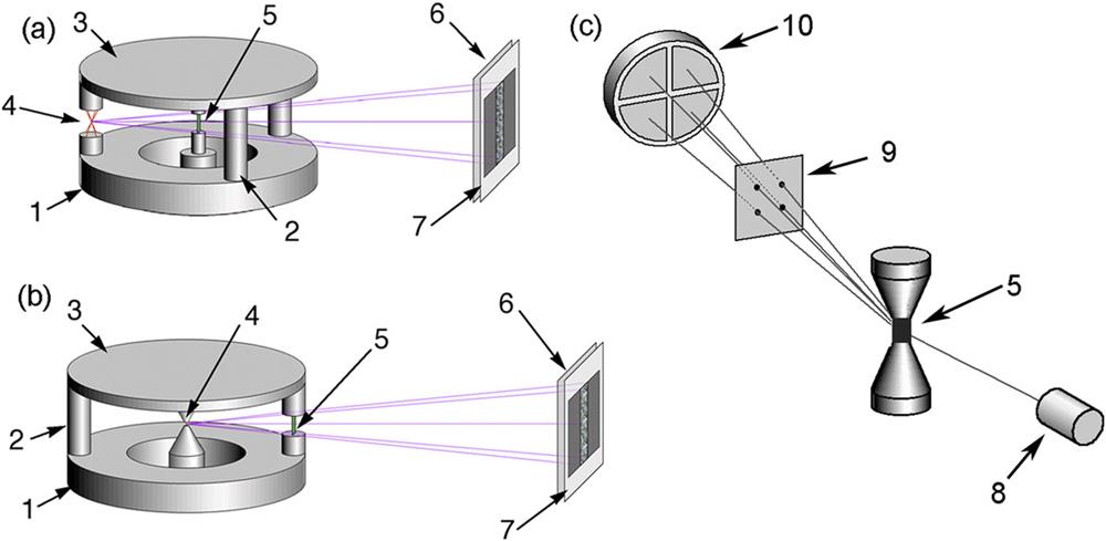
    Fig. 1. Arrangement of foils and X-pinches for radiography in the high-voltage diodes of (a) the COBRA, KING and GVP generators and (b) the XP and BIN generators, together with (c) the arrangement for obtaining UV images of the explosions of flat foils with time resolution. Key: 1, cathode plate; 2, return current rods; 3, anode plate; 4, X-pinch, 5; flat foil; 6, 12.5 μm Ti filter; 7, TR imaging plate; 8, PCD without filter; 9, pinhole camera; 10, MCP.
    Time-integrated pinhole images (side view) of exploded 4 μm Al (a) and 5 μm Cu (b) foils obtained on the XP and COBRA generators, respectively, recorded on Fuji TR imaging plates without filter. Pinholes without filter and with hole diameters of 100 μm were used. The lower energy cutoff of the pinholes in the experimental geometry was 55 eV.
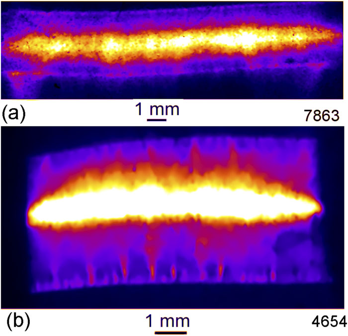
    Fig. 2. Time-integrated pinhole images (side view) of exploded 4 μm Al (a) and 5 μm Cu (b) foils obtained on the XP and COBRA generators, respectively, recorded on Fuji TR imaging plates without filter. Pinholes without filter and with hole diameters of 100 μm were used. The lower energy cutoff of the pinholes in the experimental geometry was 55 eV.
    Set of visible light framing images of an exploding 100 μm thick Al foil (3 mm wide, 8 mm long) recorded with 2 ns frame time on the COBRA generator.
    Fig. 3. Set of visible light framing images of an exploding 100 μm thick Al foil (3 mm wide, 8 mm long) recorded with 2 ns frame time on the COBRA generator.
    (a) Time-resolved pinhole images (side view) of exploded 7 μm thick Cu foil in the XUV range (Ecut > 55) recorded with 5 ns temporal resolution on the COBRA generator using a pinhole camera with 100 μm hole diameter. (b) Lineouts showing the radiation level along the width of the foil in the places marked with horizontal white lines in (a). The numbers 1–4 indicate the frames from the beginning of the current. The lower energy cutoff of the pinholes in the experimental geometry was 50 eV.
    Fig. 4. (a) Time-resolved pinhole images (side view) of exploded 7 μm thick Cu foil in the XUV range (Ecut > 55) recorded with 5 ns temporal resolution on the COBRA generator using a pinhole camera with 100 μm hole diameter. (b) Lineouts showing the radiation level along the width of the foil in the places marked with horizontal white lines in (a). The numbers 1–4 indicate the frames from the beginning of the current. The lower energy cutoff of the pinholes in the experimental geometry was 50 eV.
    Time-resolved pinhole images (side view) of exploded 7 μm thick Ni foil in the XUV range (Ecut > 55 eV) recorded with 5 ns temporal resolution on the COBRA generator using a pinhole camera with 100 μm hole diameter (shot 4661).
    Fig. 5. Time-resolved pinhole images (side view) of exploded 7 μm thick Ni foil in the XUV range (Ecut > 55 eV) recorded with 5 ns temporal resolution on the COBRA generator using a pinhole camera with 100 μm hole diameter (shot 4661).
    Time-resolved pinhole images (side view) (Ecut > 50 eV) of the initial stage of the explosion of Al foil with a thickness of 4 μm on the KING generator (shot 1013).
    Fig. 6. Time-resolved pinhole images (side view) (Ecut > 50 eV) of the initial stage of the explosion of Al foil with a thickness of 4 μm on the KING generator (shot 1013).
    Pinhole images (side view) of exploded Al foil with a thickness of 4 μm recorded in the UV radiation range (Ecut > 15 eV), with a time resolution of 5 ns on the KING generator (shot 1091).
    Fig. 7. Pinhole images (side view) of exploded Al foil with a thickness of 4 μm recorded in the UV radiation range (Ecut > 15 eV), with a time resolution of 5 ns on the KING generator (shot 1091).
    (a) Pinhole images (side view) and radiation intensity profiles of an exploding Al foil with a thickness of 4 μm, recorded in the UV radiation range (Ecut > 50 eV) with a time resolution of 5 ns on the KING generator (shot 1024). (b) Lineouts showing the radiation level along the width of the foil in the places marked with horizontal black lines in (a). The numbers 1–3 indicate frames relative to the beginning of the current.
    Fig. 8. (a) Pinhole images (side view) and radiation intensity profiles of an exploding Al foil with a thickness of 4 μm, recorded in the UV radiation range (Ecut > 50 eV) with a time resolution of 5 ns on the KING generator (shot 1024). (b) Lineouts showing the radiation level along the width of the foil in the places marked with horizontal black lines in (a). The numbers 1–3 indicate frames relative to the beginning of the current.
    Pinhole images (side view) of exploded Ti foil with a thickness of 12.5 μm, recorded in the UV radiation range (Ecut > 50 eV) with a time resolution of 5 ns on the KING generator (shot 1036). The width of the foil was 3 mm, as marked on the figure.
    Fig. 9. Pinhole images (side view) of exploded Ti foil with a thickness of 12.5 μm, recorded in the UV radiation range (Ecut > 50 eV) with a time resolution of 5 ns on the KING generator (shot 1036). The width of the foil was 3 mm, as marked on the figure.
    Point-projection images of exploding Cu foils in radiation with energy 2.5 keV E μm thick Cu foil on the COBRA generator; (b) 5 μm thick Cu foil on the XP generator; (c) 1 μm thick Cu foil on the BIN generator.
    Fig. 10. Point-projection images of exploding Cu foils in radiation with energy 2.5 keV < E < 4.8 keV: (a) 7 μm thick Cu foil on the COBRA generator; (b) 5 μm thick Cu foil on the XP generator; (c) 1 μm thick Cu foil on the BIN generator.
    Point-projection images of exploding 4 μm thick Al foils in radiation with energy 2.5 keV E < 4.8 keV on the XP generator: (a) shot 7849; (b) shot 7857; (c) shot 7872.
    Fig. 11. Point-projection images of exploding 4 μm thick Al foils in radiation with energy 2.5 keV < E < 4.8 keV on the XP generator: (a) shot 7849; (b) shot 7857; (c) shot 7872.
    Time-resolved pinhole images of exploding 7 μm thick Cu foil in the XUV range (Ecut > 55 eV), recorded with 5 ns temporal resolution on COBRA using a pinhole camera with 100 μm hole diameter (shot 3856).
    Fig. 12. Time-resolved pinhole images of exploding 7 μm thick Cu foil in the XUV range (Ecut > 55 eV), recorded with 5 ns temporal resolution on COBRA using a pinhole camera with 100 μm hole diameter (shot 3856).
    Laser shadowgrams of flat 4 μm thick Al foil (a) before and (b) after explosion, recorded on the GVP generator.
    Fig. 13. Laser shadowgrams of flat 4 μm thick Al foil (a) before and (b) after explosion, recorded on the GVP generator.
    (a) Layout of the foil in a high-voltage diode: 1, cathode; 2, return current rods; 3, anode; 4, Cu tape; 5, foil. (b) pinhole images (top view) of exploded Cu foil with a thickness of 7 μm recorded in the UV radiation range with an energy above 55 eV with a time resolution of 5 ns on the COBRA generator (shot 4658).
    Fig. 14. (a) Layout of the foil in a high-voltage diode: 1, cathode; 2, return current rods; 3, anode; 4, Cu tape; 5, foil. (b) pinhole images (top view) of exploded Cu foil with a thickness of 7 μm recorded in the UV radiation range with an energy above 55 eV with a time resolution of 5 ns on the COBRA generator (shot 4658).
    GeneratorGeneratorCurrent through
    (Institutiona)parameters I, V, trtFoilsfoils (kA)
    GVP (LPI)8 kA, 20 kV, 350 nsμm Al7.0–7.5
    KING (LPI)200 kA, 200 ns, 40 kVμm Al; 12.5 μm Ti180–200
    BIN, LPI250 kA, 300 kV, 100 ns4 and 16 µm Al; 5 µm Ni; 1 and 10 µm Cu40–80
    XP (CU)400 kA, 350 kV, 100 ns4, 12, and 16 µm Al; 5 µm Ni; 5 and 10 µm Cu; 12.5 µm Ti60–150
    COBRA (CU)1000 kA, 600 kV, 100 ns4–100 µm Al, Cu, Ti850–1000
    Table 1. Generator and load parameters.
    T. A. Shelkovenko, I. N. Tilikin, S. A. Pikuz, A. R. Mingaleev, V. M. Romanova, L. Atoyan, D. A. Hammer. Explosion dynamics of thin flat foils at high current density[J]. Matter and Radiation at Extremes, 2022, 7(5): 055901
    Download Citation