• Chinese Optics Letters
  • Vol. 15, Issue 4, 042501 (2017)
Minjuan Wang1, Linjie Zhou1、*, Haike Zhu2, Yanyang Zhou1, Yiming Zhong1, and Jianping Chen1
Author Affiliations
  • 1State Key Laboratory of Advanced Optical Communication Systems and Networks, Department of Electronic Engineering, Shanghai Jiao Tong University, Shanghai 200240, China
  • 2Advanced Technology Laboratory, Fujikura Ltd., Chiba 285-8550, Japan
  • show less
    DOI: 10.3788/COL201715.042501 Cite this Article Set citation alerts
    Minjuan Wang, Linjie Zhou, Haike Zhu, Yanyang Zhou, Yiming Zhong, Jianping Chen. Low-loss high-extinction-ratio single-drive push-pull silicon Michelson interferometric modulator[J]. Chinese Optics Letters, 2017, 15(4): 042501 Copy Citation Text show less
    (a) Schematic of the single-drive push-pull MIM. The inset shows the cross section of the modulation arms. (b) An SEM image of the fabricated MIM. The insets show the zoom-in images of the 2×2 MMI coupler and the end Sagnac loop reflectors.
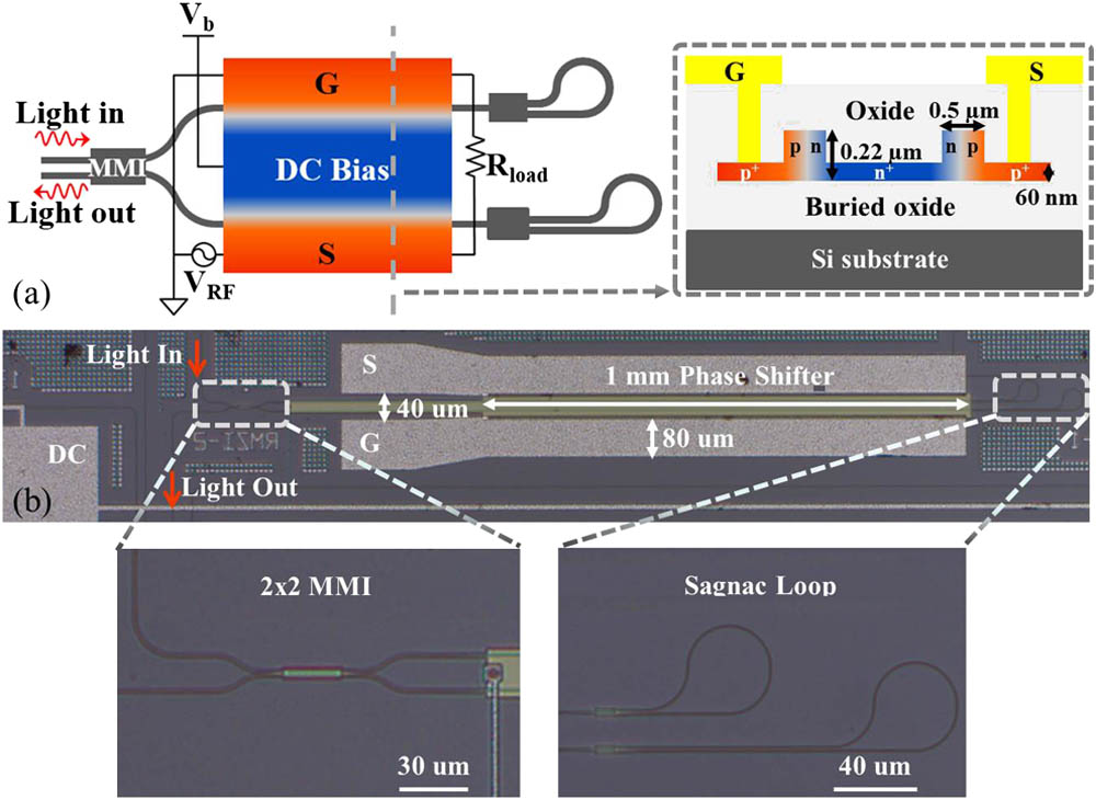
    Fig. 1. (a) Schematic of the single-drive push-pull MIM. The inset shows the cross section of the modulation arms. (b) An SEM image of the fabricated MIM. The insets show the zoom-in images of the 2×2 MMI coupler and the end Sagnac loop reflectors.
    (a) Normalized transmission spectra of the MIM under various reverse bias voltages. The inset shows the passive spectrum covering one FSR. (b) The extracted phase shift as a function of the reverse bias voltage. The red line is a fitting curve.
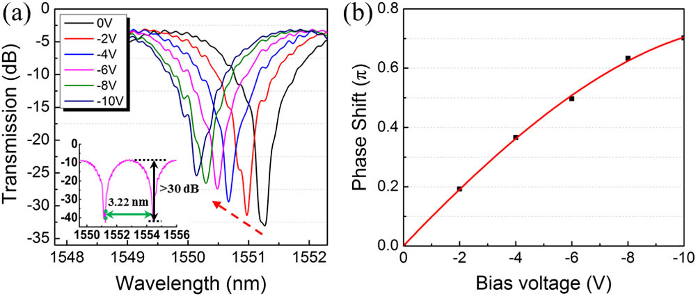
    Fig. 2. (a) Normalized transmission spectra of the MIM under various reverse bias voltages. The inset shows the passive spectrum covering one FSR. (b) The extracted phase shift as a function of the reverse bias voltage. The red line is a fitting curve.
    (a) EE S11 small signal RF response of the TWE. (b) The EO S21 response of the MIM.
    Fig. 3. (a) EE S11 small signal RF response of the TWE. (b) The EO S21 response of the MIM.
    Experimental setup for the high-speed optical modulation test. TL: tunable laser; PC: polarization controller; DUT: device under test; VOA: variable optical attenuator. The optical and electrical paths are represented by the solid and dashed lines, respectively. The dotted red box in the output upper branch shows the BER measurement setup.
    Fig. 4. Experimental setup for the high-speed optical modulation test. TL: tunable laser; PC: polarization controller; DUT: device under test; VOA: variable optical attenuator. The optical and electrical paths are represented by the solid and dashed lines, respectively. The dotted red box in the output upper branch shows the BER measurement setup.
    Measurement results for the 30 Gb/s BPSK modulation with (a) an eye diagram, (b) a constellation diagram, and (c) a demodulated eye diagram.
    Fig. 5. Measurement results for the 30 Gb/s BPSK modulation with (a) an eye diagram, (b) a constellation diagram, and (c) a demodulated eye diagram.
    Measured eye diagrams for (a) 18 Gb/s OOK, (b) 20 Gb/s OOK, (c) 18 Gbaud PAM-4, and (d) 20 Gbaud PAM-4 modulations.
    Fig. 6. Measured eye diagrams for (a) 18 Gb/s OOK, (b) 20 Gb/s OOK, (c) 18 Gbaud PAM-4, and (d) 20 Gbaud PAM-4 modulations.
    BER of the 20 Gb/s OOK modulated signal as a function of the OSNR (0.1 nm noise bandwidth) for the MIM.
    Fig. 7. BER of the 20 Gb/s OOK modulated signal as a function of the OSNR (0.1 nm noise bandwidth) for the MIM.
    Minjuan Wang, Linjie Zhou, Haike Zhu, Yanyang Zhou, Yiming Zhong, Jianping Chen. Low-loss high-extinction-ratio single-drive push-pull silicon Michelson interferometric modulator[J]. Chinese Optics Letters, 2017, 15(4): 042501
    Download Citation