• Acta Photonica Sinica
  • Vol. 51, Issue 7, 0751401 (2022)
Bingliang HU*
Author Affiliations
  • Xi’an Institute of Optics and Precision Mechanics of CAS,Xi'an 710072,China
  • show less
    DOI: 10.3788/gzxb20225107.0751401 Cite this Article
    Bingliang HU. Review of the Development of Interferometric Spectral Imaging Technology(Invited)[J]. Acta Photonica Sinica, 2022, 51(7): 0751401 Copy Citation Text show less
    The schematic diagram of optical principle of classical Michelson interferometer
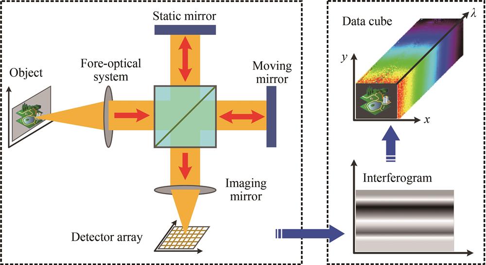
    Fig. 1. The schematic diagram of optical principle of classical Michelson interferometer
    Diagrammatic sketch of Michelson interferometer based on two corner cubes
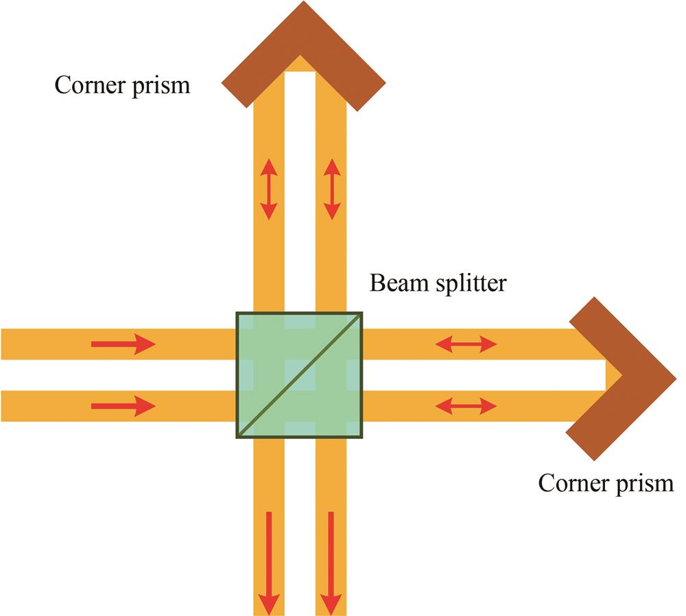
    Fig. 2. Diagrammatic sketch of Michelson interferometer based on two corner cubes
    Diagrammatic sketch of Michelson interferometer based on corner cube and mirror
    Fig. 3. Diagrammatic sketch of Michelson interferometer based on corner cube and mirror
    Schematic diagram of technical principle and structure of GIIRS
    Fig. 4. Schematic diagram of technical principle and structure of GIIRS
    Diagrammatic sketch of double ray interference spectrometer CATSI
    Fig. 5. Diagrammatic sketch of double ray interference spectrometer CATSI
    Optical principle of rotating mirror interference spectrometer
    Fig. 6. Optical principle of rotating mirror interference spectrometer
    Schematic diagram of overspeed scanning interferometer
    Fig. 7. Schematic diagram of overspeed scanning interferometer
    Ultra-rapid-scanning imaging interferometer
    Fig. 8. Ultra-rapid-scanning imaging interferometer
    Optical principle of Michelson interferometer based on rotating mirror
    Fig. 9. Optical principle of Michelson interferometer based on rotating mirror
    Spatial modulation interference spectral imager based on Sagnac transverse shear beam splitter
    Fig. 10. Spatial modulation interference spectral imager based on Sagnac transverse shear beam splitter
    Optical principle of the DASI
    Fig. 11. Optical principle of the DASI
    Structure diagram of interference spectral imager carried on Chang'e-1
    Fig. 12. Structure diagram of interference spectral imager carried on Chang'e-1
    Spectral image of an area on the lunar surface obtained by interference spectral imager carried on Chang'e-1
    Fig. 13. Spectral image of an area on the lunar surface obtained by interference spectral imager carried on Chang'e-1
    Structure diagram of EDMIS
    Fig. 14. Structure diagram of EDMIS
    Three dimensional data cube of ground object obtained by EDIS
    Fig. 15. Three dimensional data cube of ground object obtained by EDIS
    Schematic diagram of basic optical principle of spatial heterodyne spectral imaging technology
    Fig. 16. Schematic diagram of basic optical principle of spatial heterodyne spectral imaging technology
    Differential interferometer and Doppler differential interferometer with different spectral bands
    Fig. 17. Differential interferometer and Doppler differential interferometer with different spectral bands
    Sketch map of working principle of multistage micro-step mirror interference spectrometer
    Fig. 18. Sketch map of working principle of multistage micro-step mirror interference spectrometer
    The structure diagram of ALISEO
    Fig. 19. The structure diagram of ALISEO
    Structure diagram of static interference imager
    Fig. 20. Structure diagram of static interference imager
    Structure diagram of LWIR HSI
    Fig. 21. Structure diagram of LWIR HSI
    Schematic diagram of LASIS based on spatiotemporal joint modulation interferometric spectral imaging technology
    Fig. 22. Schematic diagram of LASIS based on spatiotemporal joint modulation interferometric spectral imaging technology
    Structure diagram of visible near infrared and shortwave infrared hyperspectral imager of the HJ-2A/B satellites
    Fig. 23. Structure diagram of visible near infrared and shortwave infrared hyperspectral imager of the HJ-2A/B satellites
    Pseudo color three dimensional data cube obtained by HJ-2A/B within visible to near infrared spectral range
    Fig. 24. Pseudo color three dimensional data cube obtained by HJ-2A/B within visible to near infrared spectral range
    Pseudo color three dimensional data cube obtained by HJ-2A/B within the short wave infrared spectral range
    Fig. 25. Pseudo color three dimensional data cube obtained by HJ-2A/B within the short wave infrared spectral range
    Schematic diagram of optical principle of SPIIS
    Fig. 26. Schematic diagram of optical principle of SPIIS
    Schematic diagram of optical principle of USPIIS
    Fig. 27. Schematic diagram of optical principle of USPIIS
    Schematic diagram of optical principle of SLPIIS
    Fig. 28. Schematic diagram of optical principle of SLPIIS
    ParameterValue
    Orbit altitude/km650
    Width/km50
    Spectral range/μm0.45~0.95
    Number of channele115
    Average spectral resolution/nm4.57
    Spatial resolution/m100
    Field of view/(º)-30~+30
    Semaphore/bit12
    Spectral signal to noise ratio˃50
    MTF0.24
    Radiometric calibration accuracyRelative value 2.4%,Absolute value8.2%
    Raw data rate/Mbps107.8
    Compressed data rate/bps65.7
    Mass/kg50.78
    Power/WShort-term54.6,long-term15
    Service life/year3
    Table 1. Main technical specification of interferometer
    Bingliang HU. Review of the Development of Interferometric Spectral Imaging Technology(Invited)[J]. Acta Photonica Sinica, 2022, 51(7): 0751401
    Download Citation