
Xiangyu Wang, Xi Chen, Tun Cao, Donghan Ma. Application of Adaptive Optics in Super‑Resolution Fluorescence Microscopy[J]. Chinese Journal of Lasers, 2024, 51(3): 0307104
- Chinese Journal of Lasers
- Vol. 51, Issue 3, 0307104 (2024)
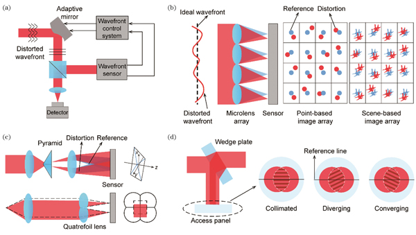
Fig. 1. Working principle of AO on basis of direct wavefront sensing. (a) Schematic of the AO system; (b) working principle of Shack-Hartmann wavefront sensor; (c) working principle of pyramid wavefront sensor (top) and partitioned aperture wavefront sensor (bottom); (d) working principle of shearing interferometer
![Application of AO in STED microscopy. (a) Schematic of STED microscopy; (b) using two SLMs to correct aberrations in both excitation and STED paths[44]; (c) using AO to align the excitation and STED paths[45]; (d) using the SLM in an off-axis holography configuration[46]; (e) using DM and SLM to correct aberrations in all the three paths[47] (S, specimen; Di, dichroic mirror; APD, avalanche photodiode; Exc., excitation beam; Emi., emission beam; QWP, quarter wave plate; PMT, photomultiplier)](/richHtml/zgjg/2024/51/3/0307104/img_02.jpg)
Fig. 2. Application of AO in STED microscopy. (a) Schematic of STED microscopy; (b) using two SLMs to correct aberrations in both excitation and STED paths[44]; (c) using AO to align the excitation and STED paths[45]; (d) using the SLM in an off-axis holography configuration[46]; (e) using DM and SLM to correct aberrations in all the three paths[47] (S, specimen; Di, dichroic mirror; APD, avalanche photodiode; Exc., excitation beam; Emi., emission beam; QWP, quarter wave plate; PMT, photomultiplier)
Fig. 3. Comparison of STED images with and without AO. (a) Imaging of axon structures of hiPSCs in dopamine neurons at a depth of 80 μm[50]; (b) imaging of astrocytes in fixed mouse brain tissues at a depth of 164 μm[55]
Fig. 4. Application of AO in 4Pi-STED microscopy[53]. S, specimen; Di, dichroic mirror; APD, avalanche photodiode; Exc., excitation beam; Emi., emission beam; RM, resonant mirror; GM, galvo mirror
Fig. 5. Comparison of SIM images with and without AO. (a) Imaging of neurites in a larval zebrafish brain at a depth of 100 μm[62]; (b) in vivo structural imaging of the mouse brain at a depth of 21‒29 μm[63]
Fig. 6. Application of AO in SIM. (a) Schematic of SIM; (b) application of AO in an OS-SIM[63]; (c) combining SIM with direct wavefront sensing[64]. S, specimen; Di, dichroic mirror; PH, pinhole; PBS, polarizing beam splitter; RM, rotatable mirror
Fig. 7. Application of AO in SMLM. (a) Schematic of SMLM imaging; (b) schematic of instrumentation-induced aberration correction with AO[67]; (c) aberration correction with the modal sensing technique[68]; (d) aberration correction with genetic algorithm[69]; (e) aberration correction with PSO[70]; (f) working principle of REALM[72]; (g) working principle of DL-AO[73]; (h) schematic of CLASS[74]. S, specimen; Di, dichroic mirror; FM, flip mirror; GM, galvo mirror; BS, beam splitter; DG, diffraction grating; PBS, polarizing beam splitter; Exc., excitation beam; Act., activation beam; Emi.,emission beam

Set citation alerts for the article
Please enter your email address
© Copyright 2018-2021 | Chinese Laser Press. All Rights Reserved 沪ICP备15018463号-20