• Matter and Radiation at Extremes
  • Vol. 7, Issue 2, 026902 (2022)
C. Samulski1, B. Srinivasan1, M. J.-E. Manuel2, R. Masti1, J. P. Sauppe3, and J. Kline3
Author Affiliations
  • 1Virginia Polytechnic Institute and State University, Blacksburg, Virginia 24060, USA
  • 2General Atomics, P.O. Box 85608, San Diego, California 92186, USA
  • 3Los Alamos National Laboratory, P.O. Box 1663, Los Alamos, New Mexico 87545, USA
  • show less
    DOI: 10.1063/5.0062168 Cite this Article
    C. Samulski, B. Srinivasan, M. J.-E. Manuel, R. Masti, J. P. Sauppe, J. Kline. Deceleration-stage Rayleigh–Taylor growth in a background magnetic field studied in cylindrical and Cartesian geometries[J]. Matter and Radiation at Extremes, 2022, 7(2): 026902 Copy Citation Text show less
    Schematic of directly driven cylindrical Omega configuration used for the validation of FLASH and for the HD, ideal-MHD, and resistive-MHD simulations. The configuration shows all relevant densities and length scales used.21
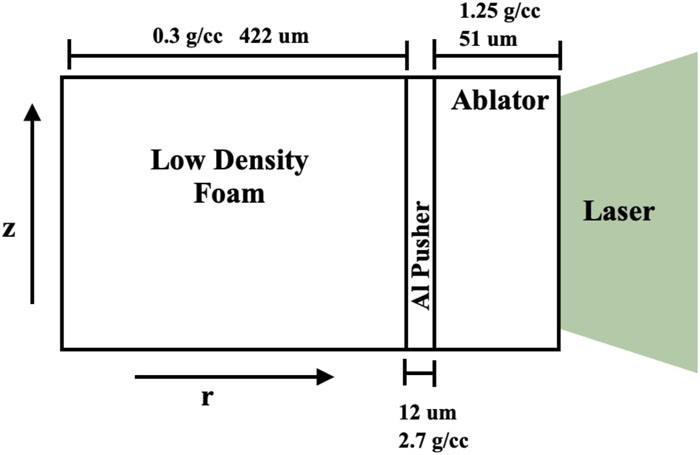
    Fig. 1. Schematic of directly driven cylindrical Omega configuration used for the validation of FLASH and for the HD, ideal-MHD, and resistive-MHD simulations. The configuration shows all relevant densities and length scales used.21
    FLASH simulation benchmarked against experimental data for the described configuration. The FLASH data are represented by the solid blue line, and the purple markers are derived from experimental data analyzed by hand, with the error bars representing the σ variation in shock position as a function of azimuthal angle.23
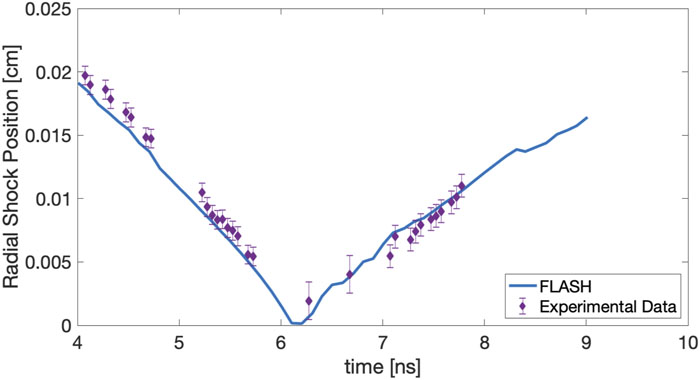
    Fig. 2. FLASH simulation benchmarked against experimental data for the described configuration. The FLASH data are represented by the solid blue line, and the purple markers are derived from experimental data analyzed by hand, with the error bars representing the σ variation in shock position as a function of azimuthal angle.23
    Density plot of cylindrical Omega-based experimental configuration from HD simulation, predicting deceleration-stage RT instability growth after 5.4 ns.
    Fig. 3. Density plot of cylindrical Omega-based experimental configuration from HD simulation, predicting deceleration-stage RT instability growth after 5.4 ns.
    RT instability growth during deceleration using cylindrical Omega experimental parameters, modeled using ideal-MHD and resistive-MHD schemes with 10, 25, and 50 T background fields.
    Fig. 4. RT instability growth during deceleration using cylindrical Omega experimental parameters, modeled using ideal-MHD and resistive-MHD schemes with 10, 25, and 50 T background fields.
    Measured growth of RT instability in the HD, ideal-MHD, and resistive-MHD simulations for the cylindrical Omega configuration. These simulations indicate that the expected diffusion of the magnetic field in resistive MHD precludes any mitigating effect on RT growth like that predicted by ideal MHD.
    Fig. 5. Measured growth of RT instability in the HD, ideal-MHD, and resistive-MHD simulations for the cylindrical Omega configuration. These simulations indicate that the expected diffusion of the magnetic field in resistive MHD precludes any mitigating effect on RT growth like that predicted by ideal MHD.
    Maximum magnetic field in the simulation domain during the course of the implosion for the 10, 25, and 50 T ideal-MHD and resistive-MHD cases. The ideal-MHD cases have consistently higher peak magnetic fields until maximum compression.
    Fig. 6. Maximum magnetic field in the simulation domain during the course of the implosion for the 10, 25, and 50 T ideal-MHD and resistive-MHD cases. The ideal-MHD cases have consistently higher peak magnetic fields until maximum compression.
    Schematic of the cylindrical NIF configuration developed for simulations in HD, ideal-MHD, and resistive-MHD models. The cylindrical target for NIF consists of a 30 μm thick solid-density CH ablator, a nickel-doped foam pusher of thickness 300 μm at a density of 0.215 g cm−3, and a low-density CH foam of 0.02 g cm−3 and thickness 1.6 mm, as seen in Fig. 7. A perturbation with λ = 120 μm and a sinusoidal amplitude of 40 μm is added to the nickel-doped foam at the interface with the low-density target foam.
    Fig. 7. Schematic of the cylindrical NIF configuration developed for simulations in HD, ideal-MHD, and resistive-MHD models. The cylindrical target for NIF consists of a 30 μm thick solid-density CH ablator, a nickel-doped foam pusher of thickness 300 μm at a density of 0.215 g cm−3, and a low-density CH foam of 0.02 g cm−3 and thickness 1.6 mm, as seen in Fig. 7. A perturbation with λ = 120 μm and a sinusoidal amplitude of 40 μm is added to the nickel-doped foam at the interface with the low-density target foam.
    Density plots 14.6 ns into the implosion for the cylindrical NIF experimental parameters, modeled using the HD, ideal-MHD, and resistive-MHD schemes, the latter two with a 30 T background field. Differences in RT spike height and morphology between the different models can be seen, and, in particular, the difference in RT bubble shape between the HD and resistive-MHD cases should be noted.
    Fig. 8. Density plots 14.6 ns into the implosion for the cylindrical NIF experimental parameters, modeled using the HD, ideal-MHD, and resistive-MHD schemes, the latter two with a 30 T background field. Differences in RT spike height and morphology between the different models can be seen, and, in particular, the difference in RT bubble shape between the HD and resistive-MHD cases should be noted.
    HD, 30 T ideal-MHD, and 30 T resistive-MHD plots of the magnetic Reynolds number at 14.6 ns using cylindrical NIF experimental parameters. The magnetic Reynolds numbers are comparable between HD and ideal-MHD, with both being close to 5 within the RT spikes and reaching 10 in the plasma in front of the RT instability bubbles.
    Fig. 9. HD, 30 T ideal-MHD, and 30 T resistive-MHD plots of the magnetic Reynolds number at 14.6 ns using cylindrical NIF experimental parameters. The magnetic Reynolds numbers are comparable between HD and ideal-MHD, with both being close to 5 within the RT spikes and reaching 10 in the plasma in front of the RT instability bubbles.
    Plasma β for the 30 T ideal-MHD and resistive-MHD cases at 14.6 ns using cylindrical NIF experimental parameters. The plasma β is of the order of several hundred within the RT bubbles and of the order of 100 in front of the RT spikes in the resistive-MHD case. In the ideal-MHD case, the plasma β is of the order of a few tens in and around the RT spike growth and a 100 within the RT spikes themselves.
    Fig. 10. Plasma β for the 30 T ideal-MHD and resistive-MHD cases at 14.6 ns using cylindrical NIF experimental parameters. The plasma β is of the order of several hundred within the RT bubbles and of the order of 100 in front of the RT spikes in the resistive-MHD case. In the ideal-MHD case, the plasma β is of the order of a few tens in and around the RT spike growth and a 100 within the RT spikes themselves.
    RT instability growth in HD, ideal-MHD, and resistive-MHD simulations measured in the cylindrical NIF-based configuration. The HD RT spike growth is shown by the black full line, the 30 T ideal-MHD growth by the blue dashed line, and the 30 T resistive-MHD spike growth by the blue dotted line. A difference in RT spikes can be noted after 8 ns, and thus the difference between the HD and resistive-MHD spike sizes could be experimentally measurable with axial radiographs.
    Fig. 11. RT instability growth in HD, ideal-MHD, and resistive-MHD simulations measured in the cylindrical NIF-based configuration. The HD RT spike growth is shown by the black full line, the 30 T ideal-MHD growth by the blue dashed line, and the 30 T resistive-MHD spike growth by the blue dotted line. A difference in RT spikes can be noted after 8 ns, and thus the difference between the HD and resistive-MHD spike sizes could be experimentally measurable with axial radiographs.
    Schematic of the general configuration used for directly driven planar targets on Omega. These targets consist of a high-density nickel-doped foam with a sinusoidal perturbation with wavelength λ = 80 μm and an amplitude of 20 μm incident on a low-density CH foam.
    Fig. 12. Schematic of the general configuration used for directly driven planar targets on Omega. These targets consist of a high-density nickel-doped foam with a sinusoidal perturbation with wavelength λ = 80 μm and an amplitude of 20 μm incident on a low-density CH foam.
    Density plots of Omega-scale planar targets. The RT instability growth is shown at 7 ns during deceleration simulated in HD and ideal-MHD schemes with a 12 T background magnetic field.
    Fig. 13. Density plots of Omega-scale planar targets. The RT instability growth is shown at 7 ns during deceleration simulated in HD and ideal-MHD schemes with a 12 T background magnetic field.
    Magnetic Reynolds number of the Omega-scale planar target at 7 ns during deceleration in HD and 12 T ideal-MHD simulations. Note the magnetic Reynolds numbers in the 5–8 range for both models.
    Fig. 14. Magnetic Reynolds number of the Omega-scale planar target at 7 ns during deceleration in HD and 12 T ideal-MHD simulations. Note the magnetic Reynolds numbers in the 5–8 range for both models.
    Density plots of RT instability growth during deceleration using planar NIF experimental parameters, modeled using HD, ideal-MHD, and resistive MHD schemes, the latter two with 30 T background field, 12 ns into the implosion. There are clear differences in RT spike height and morphology between the different models, with the ideal-MHD model predicting significantly damped RT spike growth.
    Fig. 15. Density plots of RT instability growth during deceleration using planar NIF experimental parameters, modeled using HD, ideal-MHD, and resistive MHD schemes, the latter two with 30 T background field, 12 ns into the implosion. There are clear differences in RT spike height and morphology between the different models, with the ideal-MHD model predicting significantly damped RT spike growth.
    Plots of the magnetic Reynolds number of the plasma in and around the RT spike growth at 12 nsobtained from HD, ideal-MHD, and resistive-MHD simulations using planar NIF experimental parameters. The magnetic Reynolds number differs slightly between the HD, ideal-MHD, and resistive-MHD results, but ultimately lies close to 40 in each case.
    Fig. 16. Plots of the magnetic Reynolds number of the plasma in and around the RT spike growth at 12 nsobtained from HD, ideal-MHD, and resistive-MHD simulations using planar NIF experimental parameters. The magnetic Reynolds number differs slightly between the HD, ideal-MHD, and resistive-MHD results, but ultimately lies close to 40 in each case.
    Plots of the plasma β of the plasma in and around the RT spike growth at 12 ns obtained from HD, ideal-MHD, and resistive-MHD simulations using planar NIF experimental parameters. Note that the plasma β is of the order of 100 in front of the RT spikes and significantly higher inside the spikes.
    Fig. 17. Plots of the plasma β of the plasma in and around the RT spike growth at 12 ns obtained from HD, ideal-MHD, and resistive-MHD simulations using planar NIF experimental parameters. Note that the plasma β is of the order of 100 in front of the RT spikes and significantly higher inside the spikes.
    Measured growth of RT instability from HD, ideal-MHD, and resistive-MHD simulations for planar NIF-based experimental configurations. The HD RT growth is shown by the black solid line, the 30 T ideal-MHD growth by the blue dashed line, and the 30 T resistive-MHD growth by the blue dotted line. A measurable difference in RT instability growth is notable after 10 ns.
    Fig. 18. Measured growth of RT instability from HD, ideal-MHD, and resistive-MHD simulations for planar NIF-based experimental configurations. The HD RT growth is shown by the black solid line, the 30 T ideal-MHD growth by the blue dashed line, and the 30 T resistive-MHD growth by the blue dotted line. A measurable difference in RT instability growth is notable after 10 ns.
    ConfigurationT (eV)RmβχPeLRe
    Omega cylindrical, resistive-MHD, 25 T18.71.026070.00464567 035
    Omega cylindrical, ideal-MHD, 25 T17.10.951110.0275786 392
    Omega cylindrica,l HD, 0 T18.50.9972071 601
    NIF cylindrical, resistive-MHD, 30 T53.17.53280.061306 350
    NIF cylindrical, ideal-MHD, 30 T52.96.1380.151075 234
    NIF cylindrical, HD, 0 T63.48.51155 628
    NIF planar, resistive-MHD, 30 T81.242.64340.281108 378
    NIF planar, ideal-MHD, 30 T81.941.93240.231088 109
    NIF planar, HD, 0 T8246.41165 933
    Table 1. Plasma parameters of RT instability at 90% pusher: temperature T, magnetic Reynolds number Rm, plasma β, ln Λ, Hall parameter χ, Péclet number PeL, and Reynolds number Re.
    ConfigurationT (eV)RmβχPeLRe
    Omega cylindrical, resistive-MHD, 25 T35.91.96130.016965027
    Omega cylindrical, ideal-MHD, 25 T33.61.81650.031146109
    Omega cylindrical, HD, 0 T34.71.8985171
    NIF cylindrical, resistive-MHD, 30 T56.414.71660.091064265
    NIF cylindrical, ideal-MHD, 30 T56.112.5410.15973942
    NIF cylindrical, HD, 0 T59.815.7943699
    NIF planar, resistive-MHD, 30 T80.943990.211133995
    NIF planar, ideal-MHD, 30 T81.142.6520.391053883
    NIF planar, HD, 0 T82.145.11214204
    Table 2. Plasma parameters of RT instability at 90% low-density foam: temperature T, magnetic Reynolds number Rm, plasma β, ln Λ, Hall parameter χ, Péclet number PeL, and Reynolds number Re.
    C. Samulski, B. Srinivasan, M. J.-E. Manuel, R. Masti, J. P. Sauppe, J. Kline. Deceleration-stage Rayleigh–Taylor growth in a background magnetic field studied in cylindrical and Cartesian geometries[J]. Matter and Radiation at Extremes, 2022, 7(2): 026902
    Download Citation