
C. Samulski, B. Srinivasan, M. J.-E. Manuel, R. Masti, J. P. Sauppe, J. Kline. Deceleration-stage Rayleigh–Taylor growth in a background magnetic field studied in cylindrical and Cartesian geometries[J]. Matter and Radiation at Extremes, 2022, 7(2): 026902
- Matter and Radiation at Extremes
- Vol. 7, Issue 2, 026902 (2022)
Abstract
I. INTRODUCTION
Pre-magnetization of inertial confinement fusion (ICF) targets has been proposed as a means to achieve high energy gain due to the reduced ignition threshold and increased yield.1,2 One of the instabilities identified as a primary contributor to degradation of ICF implosions3,4 is the Rayleigh–Taylor (RT) instability.5,6 The presence of the RT instability in an ICF capsule disrupts convergence, which in turn can reduce the hot-spot temperatures necessary for ignition. Although RT spikes are predicted to generate magnetic fields in the hotspot, they do not significantly alter the hydrodynamics (HD) or thermal conduction.7–9
Mitigation of the growth of the RT instability10–12 and fuel–ablator mixing13–16 in ICF implosions is pivotal to improving capsule performance. One scheme aimed at achieving this is the use of strong pre-seeded magnetic fields.1,17 RT instability in the ablative acceleration phase of ICF implosion has been extensively studied both computationally and experimentally, but it is deceleration-phase RT instability that has a direct effect on the hotspot. The deceleration phase occurs when the low-density, high-pressure interior begins pushing back on the higher-density, lower-pressure imploding liner. Some theoretical work18,19 has been performed, and experimental efforts20–24 are beginning to probe cylindrical implosions in unmagnetized targets specifically to study deceleration-phase RT instability in a converging geometry. Additionally, a great deal of work has been done on planar blast-wave-driven RT instability growth,25–30 particularly in an astrophysical context, though most of the magnetization taken into consideration has been explored in the context of self-generated magnetic fields.31–34
Magneto-RT (MRT) instabilities are known to occur in the cylindrical geometry of imploding liners in pulsed-power magneto-inertial fusion experiments such as Magnetized Liner Inertial Fusion (MagLIF).35,36 Experiments have measured MRT growth on the Z facility and have compared it with MRT theory in cylindrical geometry.37 The presence of seeded axial magnetic fields in combination with the azimuthal magnetic fields that occur in a Z pinch could significantly affect RT instability growth and development in MagLIF.38,39 Hence, investigating the effect of magnetic fields on the development of RT instability in cylindrical geometry can play a significant role in mitigating the growth of the instability in laser- and pulsed-power-driven fusion concepts.
The standard evolution of the RT instability is commonly understood via the classical description of two fluids with differing densities ρ1 and ρ2 (with ρ2 > ρ1) subject to a constant acceleration g opposing the density gradient. A perturbation at the interface with wavenumber k = 2π/λ results in a growth rate of
A magnetic field inside an ICF implosion will be amplified by magnetic flux compression.1,2 Owing to this amplification, magnetic fields are predicted to affect the RT spike morphology and subsequent evolution of the Kelvin–Helmholtz (KH) instability.1,10 The level of field amplification is characterized by the magnetic Reynolds number Rm, which is a measure of the ratio of fluid advection to magnetic diffusion. When Rm ≫ 1, the fluid is highly conducting, and a seeded magnetic field is approximately frozen-in.1 Plasma conditions in the hotspot produce an Rm of ∼104, suggesting amplification factors of several hundred.11 Under these conditions, an appropriately applied seed magnetic field may help reduce RT growth and mixing in the hotspot, improving the efficiency of the implosion.
Deceleration-phase RT instability has the potential to truly disrupt convergence of ICF implosions by mixing the cold ablator with the hot fuel. The use of appropriately aligned seeded magnetic fields can produce conditions in which the RT instability could be mitigated with sufficient amplification (Rm ≫ 1). Additionally, the ratio of dynamic pressure to magnetic pressure, β = 2μ0ρu2/B2, characterizes the level to which the magnetic field can alter hydrodynamic evolution. Hydrodynamic systems with a low beta (β ≲ 1) will be greatly affected by a magnetic field. Recent computational and experimental work12 suggests that morphological effects in deceleration-phase RT evolution begin to occur at β ≲ 100.
The work presented here studies the effect of magnetic fields on the RT instability in planar and cylindrical geometries. Planar geometry is relatively simple to diagnose, while cylinders allow diagnostic access and incorporate the effects of geometric convergence. Cylinders have been used to study hydrodynamic instabilities for many years,42–44 and the Los Alamos National Laboratory has recently revitalized such a platform.21–23 Both the planar target and the cylinder consist of a high-density pusher layer that is accelerated into a lower-density foam via laser direct drive. This work considers targets designed for both Omega45 and the National Ignition Facility (NIF).46 With additional development, seeded background magnetic fields of ∼30 T may become accessible on NIF and Omega, and so a solid-density Omega-scale cylindrical configuration and a foam configuration for Omega-scale planar and NIF-scale cylindrical and planar targets are simulated.
Understanding the potential effects of a seed magnetic field on RT instability growth is the primary motivation for this work. A large magnetic Reynolds number is required to access the regimes where magnetic stabilization can occur, but this requires sufficiently high temperatures. This is evident in the standard Spitzer resistivity model, where the resistive diffusion of the magnetic field scales inversely with temperature. The standard model of using resistivity for an ICF implosion requires that the resistivity be sufficiently small that diffusive effects are limited. The work presented here focuses on simulations performed using radiation hydrodynamics only (HD), ideal-magnetohydrodynamics (MHD), or resistive MHD models in cylindrical and planar geometries.
The remainder of the paper is structured as follows. Section II presents code descriptions for FLASH. Section III presents the results of simulations using a cylindrical design at Omega and the NIF, and Sec. IV presents the results of simulations of experiments on Omega and the NIF using a planar platform. Conclusions are presented in Sec. V.
The key contributions of this paper are as follows. First, this work compares the expected results for a magnetized solid-density ICF target with those of a novel foam target design. Second, it predicts relevant parameters necessary to achieve the desired temperatures and magnetic Reynolds numbers under which a magnetized ICF experiment will see the mitigating effects of an externally applied magnetic field.
II. NUMERICAL MODEL
The models and numerical methods used are briefly outlined in this section. FLASH is an Eulerian multiphysics radiation-hydrodynamics code developed by the FLASH Center, now located at the University of Rochester,47 with adaptive mesh refinement capabilities, which are used to solve hyperbolic and stiff parabolic systems. The ICF configurations presented are modeled with the Euler equations, the ideal-MHD equations, and the resistive-MHD equations from FLASH.48 The specific Euler equations used in this study are given as49
The resistive-MHD cases presented use a Spitzer form50 of resistivity in the FLASH code given by49
III. CYLINDRICAL CONFIGURATIONS
A. Cylindrical model tuning
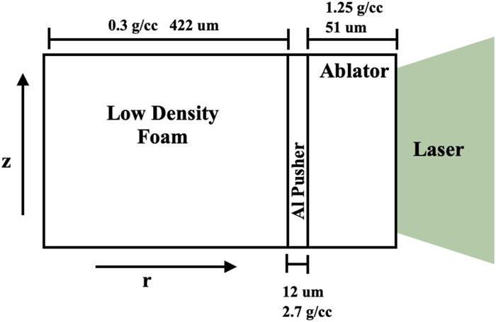
The parameters used for the cylindrical simulations, performed by modeling targets in two dimensions in the radial and axial (r–z) frame of reference, are derived from an experiment performed using the Omega laser facility. In particular, the configuration derived for the verification of FLASH can been seen in Fig. 1.21 Using a laser drive of 18 kJ over 1 ns, 2D FLASH simulations are verified against existing experimental data from Omega shots whose configuration can be found in Ref. 23.
![]()
Figure 1.Schematic of directly driven cylindrical Omega configuration used for the validation of FLASH and for the HD, ideal-MHD, and resistive-MHD simulations. The configuration shows all relevant densities and length scales used.
FLASH calculations of the radial shock location are shown to agree well with experimental data collected over a series of four shots; see Fig. 2. As can be seen from this comparison, FLASH shows very reasonable agreement with the shock trajectories extracted from the available experimental data. This provides confidence in FLASH’s ability to simulate the bulk hydrodynamic motion in an r–z geometry that dictates RT instability growth during the deceleration phase.
![]()
Figure 2.FLASH simulation benchmarked against experimental data for the described configuration. The FLASH data are represented by the solid blue line, and the purple markers are derived from experimental data analyzed by hand, with the error bars representing the
B. Cylindrical RT instability on Omega
The simulations to address magnetic field effects on cylindrical RT instability are based on a recent design study20 where the density of the low-density foam is decreased to 0.06 g cm−3. A lower laser drive of 8 kJ is used in this work. A perturbation along the z direction with λ = 40 μm and a sinusoidal amplitude of 5 μm is added to the interior aluminum tracer surface. These simulations are performed using FLASH’s HD, ideal-MHD, and resistive-MHD schemes. The seed background magnetic field for the MHD cases oriented parallel to the perturbation vector are 10, 25, and 50 T. The configuration was deliberately chosen so that the perturbation wavelength would be larger than λc. The values of λc for the three cases presented are 0.03, 0.17, and 0.7 μm, corresponding to magnetic fields of 10, 25, and 50 T, respectively. Distinct RT instability growth is noted on the interior of the shell during the deceleration phase of the implosion when modeled using the HD scheme; see Fig. 3.
![]()
Figure 3.Density plot of cylindrical Omega-based experimental configuration from HD simulation, predicting deceleration-stage RT instability growth after 5.4 ns.
Figure 4 illustrates this solid-density configuration modeled using the ideal-MHD and resistive-MHD schemes 5.4 ns into the implosion at 10, 25, and 50 T. The ideal-MHD density plots show that the nonlinear evolution modeled in these simulations produces stronger reduction in growth at higher seed magnetic field strengths. The ideal-MHD simulations at 10 T show little difference in morphology when compared with the HD case, while the 25 T case illustrates how the RT bubble morphology is reduced in the ideal-MHD case compared with the HD case. At 50 T, the overall morphology and growth of the RT spikes are more significantly affected by the reduced growth in the ideal-MHD simulation than in the HD simulation. While the ideal-MHD results show progressively clearer and notable reductions in RT spike growth and morphology, in the resistive-MHD simulations, the addition of the diffusive effects of resistivity to Eq. (8) reduces the magnetic field amplification during the implosion. This in turn reduces the effect of the magnetic fields on RT spike growth.
![]()
Figure 4.RT instability growth during deceleration using cylindrical Omega experimental parameters, modeled using ideal-MHD and resistive-MHD schemes with 10, 25, and 50 T background fields.
The magnetic fields that are presently achievable and those that are expected to be achievable in the next generation of coil designs have little impact on the RT spike growth when a resistive-MHD model is used. This can clearly be seen in Fig. 5, which shows the measurements over the course of the implosion of the RT spike growth from the top of the RT instability bubble (the peak) to the lowest point between RT spikes (the valley). As such, it predicts that the ideal-MHD regime provides an up to 40 μm measurable reduction in RT spike growth, whereas the HD and resistive-MHD schemes present an RT spike growth difference of the order of only a few micrometers. This suggests that in the case of solid-density shells, with small seed background fields, the HD case would capture the expected RT instability growth and morphology that a resistive-MHD scheme would predict. This is notable, given that in the resistive-MHD cases, the magnetic field amplification is of the order of three times the seeded field in the surrounding plasma for 50, 25, and 10 T seed fields in comparison with 400, 300, and 200 T, respectively, for the ideal-MHD cases corresponding to the same seed fields. Figure 6 reveals significant amplification of the magnetic field in the ideal-MHD and resistive-MHD cases; however, the resistive-MHD amplification is located in the shock front, whereas the ideal-MHD amplification occurs in the region where the RT instability grows behind the shock. Additionally, the resistive-MHD magnetic field only exceeds the ideal-MHD one when peak compression occurs, which is likely due to the peak magnetic field being located in the shock front in the resistive-MHD cases and reaching the central axis of the cylinder earlier in time than in the ideal-MHD cases. As a result of the large magnetic field amplification that is occurring, the field exceeds other magnetic fields, such as the self-generated Biermann battery magnetic field. The lower temperatures and magnetic Reynolds numbers associated with these solid-density cylindrical implosions are responsible for the reduced effect of the magnetic fields on the growth of RT instability.
![]()
Figure 5.Measured growth of RT instability in the HD, ideal-MHD, and resistive-MHD simulations for the cylindrical Omega configuration. These simulations indicate that the expected diffusion of the magnetic field in resistive MHD precludes any mitigating effect on RT growth like that predicted by ideal MHD.
![]()
Figure 6.Maximum magnetic field in the simulation domain during the course of the implosion for the 10, 25, and 50 T ideal-MHD and resistive-MHD cases. The ideal-MHD cases have consistently higher peak magnetic fields until maximum compression.
The ideal-MHD cases produce temperatures in and around the unstable interface of the order of 25 and 16 eV within the RT bubbles and spikes, respectively. These low temperatures correspond to low estimated magnetic Reynolds numbers of ∼3 near the interface. By comparison, the resistive-MHD cases produce comparable plasma temperatures and magnetic Reynolds numbers of ∼6, giving a clear indication that field amplification is insufficient to produce fields strong enough to alter RT evolution in a measurable way. To achieve higher magnetic Reynolds numbers, the laser drive should be increased and the pusher density reduced to increase the temperatures near the unstable interface.
C. Cylindrical RT instability on the NIF
The cylindrical NIF configuration is based on a set of NIF-scaled Omega parameters,22 which leads to a direct-drive NIF laser energy of 226 kJ. A modification is made to the cylindrical target that switches the solid-density Al marker for a nickel-doped foam, motivated by planar target designs that will be discussed subsequently. The cylindrical target for NIF is illustrated in Fig. 7, where the pusher has been adjusted to be a high-density nickel-doped foam. A perturbation with λ = 120 μm and an sinusoidal amplitude of 40 μm, chosen to be larger than the critical wavelength of 6 μm, is added to the nickel-doped foam at the interface with the low-density target foam. This configuration is simulated with only a 30 T magnetic field, comparable to those previously achieved on the NIF.
![]()
Figure 7.Schematic of the cylindrical NIF configuration developed for simulations in HD, ideal-MHD, and resistive-MHD models. The cylindrical target for NIF consists of a 30
The difference in RT spike size and morphology between the HD and ideal-MHD cases is again notable, as can be seen from Fig. 8. However, unlike in the previously discussed Omega configuration, which uses a solid-density Al marker, Fig. 8 shows that the resistive-MHD model also predicts a difference in the RT bubble compared with the HD model. Differences between the resistive-MHD simulation on the one hand and the HD and ideal-MHD simulations on the other are seen in the RT morphology of the bubble and spike. As can be seen below in Fig. 11, however, the overall spike growth does not different significantly between the HD and resistive-MHD cases, until late in time. All three models show the RT spikes developing well behind the shock front, which is the region where the highest temperatures are reached. Consequently, the plasma in and around the RT spikes reaches temperatures of the order of 60 eV.
![]()
Figure 8.Density plots 14.6 ns into the implosion for the cylindrical NIF experimental parameters, modeled using the HD, ideal-MHD, and resistive-MHD schemes, the latter two with a 30 T background field. Differences in RT spike height and morphology between the different models can be seen, and, in particular, the difference in RT bubble shape between the HD and resistive-MHD cases should be noted.
The magnetic Reynolds numbers, shown in Fig. 9, only reach ∼5 in the bubble and ∼10 in front of the RT spikes. These low magnetic Reynolds numbers are in part due to the temperature and decreasing velocities of the plasma during the deceleration. The low magnetic Reynolds numbers result in low magnetic field amplification. Figure 10 shows the plasma β values reaching several thousand at the center of the RT instability bubbles and dropping rapidly to ∼50 at the front of the RT spike growth. At these β levels, the system is only beginning to approach the regime where morphological magnetic field effects may be expected.
![]()
Figure 9.HD, 30 T ideal-MHD, and 30 T resistive-MHD plots of the magnetic Reynolds number at 14.6 ns using cylindrical NIF experimental parameters. The magnetic Reynolds numbers are comparable between HD and ideal-MHD, with both being close to 5 within the RT spikes and reaching 10 in the plasma in front of the RT instability bubbles.
![]()
Figure 10.Plasma
Despite the RT instability morphology being different in the resistive-MHD case, the resistive-MHD simulations with a 30 T seed magnetic field reveal little reduction in RT spike size, as can be seen in Fig. 11. Specifically, secondary features seen growing at the top of the RT instability bubbles in the HD case are reduced in size, as shown in Fig. 8. The late-time difference in spike size between the HD and resistive-MHD cases from Fig. 11 reaches 50 μm when, optimistically, the secondary features growing on top of the spikes in the HD case are incorporated; this may be measurable experimentally with axial radiographs. The detailed morphology of these small-scale secondary features would be significantly more difficult to measure in an experiment than a simple reduction in spike size.
![]()
Figure 11.RT instability growth in HD, ideal-MHD, and resistive-MHD simulations measured in the cylindrical NIF-based configuration. The HD RT spike growth is shown by the black full line, the 30 T ideal-MHD growth by the blue dashed line, and the 30 T resistive-MHD spike growth by the blue dotted line. A difference in RT spikes can be noted after 8 ns, and thus the difference between the HD and resistive-MHD spike sizes could be experimentally measurable with axial radiographs.
Tables I and II provide approximate values for important plasma parameters for all the configurations at locations within the RT spikes where the material is 90% pusher and 90% low-density foam, respectively. Note that for the Omega cylindrical configuration, the temperature, Hall parameter χ, and Rm are substantially smaller than for the NIF cylindrical configuration, whereas the Reynolds number Re and Péclet number PeL are larger in the Omega cases than in the NIF cases. Additionally, the difference between the pusher-dominant region (Table I) and the low-density foam-dominant region (Table II) of the RT instability lies primarily in the temperature and plasma β, with small differences between the regions in Rm but substantial differences in Re and PeL. The planar configurations discussed in Sec. IV achieve notably higher temperatures and Rm, while maintaining small Hall parameter values along with large Reynolds and Péclet numbers.
| Configuration | T (eV) | Rm | β | χ | PeL | Re |
|---|---|---|---|---|---|---|
| Omega cylindrical, resistive-MHD, 25 T | 18.7 | 1.0 | 2607 | 0.004 | 645 | 67 035 |
| Omega cylindrical, ideal-MHD, 25 T | 17.1 | 0.95 | 111 | 0.02 | 757 | 86 392 |
| Omega cylindrica,l HD, 0 T | 18.5 | 0.99 | ⋯ | ⋯ | 720 | 71 601 |
| NIF cylindrical, resistive-MHD, 30 T | 53.1 | 7.5 | 328 | 0.06 | 130 | 6 350 |
| NIF cylindrical, ideal-MHD, 30 T | 52.9 | 6.1 | 38 | 0.15 | 107 | 5 234 |
| NIF cylindrical, HD, 0 T | 63.4 | 8.5 | ⋯ | ⋯ | 115 | 5 628 |
| NIF planar, resistive-MHD, 30 T | 81.2 | 42.6 | 434 | 0.28 | 110 | 8 378 |
| NIF planar, ideal-MHD, 30 T | 81.9 | 41.9 | 324 | 0.23 | 108 | 8 109 |
| NIF planar, HD, 0 T | 82 | 46.4 | ⋯ | ⋯ | 116 | 5 933 |
Table 1. Plasma parameters of RT instability at 90% pusher: temperature T, magnetic Reynolds number Rm, plasma β, ln Λ, Hall parameter χ, Péclet number PeL, and Reynolds number Re.
| Configuration | T (eV) | Rm | β | χ | PeL | Re |
|---|---|---|---|---|---|---|
| Omega cylindrical, resistive-MHD, 25 T | 35.9 | 1.9 | 613 | 0.016 | 96 | 5027 |
| Omega cylindrical, ideal-MHD, 25 T | 33.6 | 1.8 | 165 | 0.03 | 114 | 6109 |
| Omega cylindrical, HD, 0 T | 34.7 | 1.8 | ⋯ | ⋯ | 98 | 5171 |
| NIF cylindrical, resistive-MHD, 30 T | 56.4 | 14.7 | 166 | 0.09 | 106 | 4265 |
| NIF cylindrical, ideal-MHD, 30 T | 56.1 | 12.5 | 41 | 0.15 | 97 | 3942 |
| NIF cylindrical, HD, 0 T | 59.8 | 15.7 | ⋯ | ⋯ | 94 | 3699 |
| NIF planar, resistive-MHD, 30 T | 80.9 | 43 | 99 | 0.21 | 113 | 3995 |
| NIF planar, ideal-MHD, 30 T | 81.1 | 42.6 | 52 | 0.39 | 105 | 3883 |
| NIF planar, HD, 0 T | 82.1 | 45.1 | ⋯ | ⋯ | 121 | 4204 |
Table 2. Plasma parameters of RT instability at 90% low-density foam: temperature T, magnetic Reynolds number Rm, plasma β, ln Λ, Hall parameter χ, Péclet number PeL, and Reynolds number Re.
IV. PLANAR CONFIGURATIONS
Given the solid densities used in the Omega cylindrical configuration and the primarily morphological effects of the seed magnetic field in the NIF cylindrical configuration, an effort is made to explore planar foam targets on Omega and NIF-scale powers.
A. Planar RT instability on Omega
Additional configurations are designed to study blast-wave-driven deceleration-stage growth of RT instability, utilizing a laser to drive the implosion of a planar target in which a high-density pusher foam is machined with a sinusoidal perturbation and is driven into a low-density foam, as illustrated in Fig. 12. A seed background magnetic field of 12 T is applied in the ideal-MHD simulation. This target is then directly driven with a 2350 J laser drive for 2 ns, comparable to an Omega-EP experimental drive.
![]()
Figure 12.Schematic of the general configuration used for directly driven planar targets on Omega. These targets consist of a high-density nickel-doped foam with a sinusoidal perturbation with wavelength
The RT instability growth is prominent during the deceleration stage, as can be seen from the density plots in Fig. 13. Distinct small-scale features are present in the HD cases, but are damped in the ideal-MHD cases, alongside an overall reduction in RT spike size. Additionally, the temperatures observed in these simulations are of the order of 40–45 eV in and around the RT instability, which is twice as hot as in the previously discussed cylindrical Omega-scale target simulations. This increased temperature does result in a estimated magnetic Reynolds number that is higher in both the HD and ideal-MHD cases, as can be seen from Fig. 14; however, it is still only of the order of 5–8, and thus is still too small for the effect of the 12 T seeded background magnetic field to be measurable in a resistive-MHD case. Consequently, shifting again to a NIF-like regime allows high laser drives, which would result in higher temperatures and higher magnetic Reynolds numbers. This then increases the likelihood that a resistive-MHD simulation would lead to an RT spike growth that differs from the growth found in HD simulations.
![]()
Figure 13.Density plots of Omega-scale planar targets. The RT instability growth is shown at 7 ns during deceleration simulated in HD and ideal-MHD schemes with a 12 T background magnetic field.
![]()
Figure 14.Magnetic Reynolds number of the Omega-scale planar target at 7 ns during deceleration in HD and 12 T ideal-MHD simulations. Note the magnetic Reynolds numbers in the 5–8 range for both models.
B. Planar RT instability on the NIF
The planar configuration explored here is based on experimental parameters that are the design point for a direct-drive NIF campaign and consist of a 30 μm thick CH ablator of density 1.0 g cm−3, a 400 μm thick CH foam of density 0.215 g cm−3, and a 400 μm thick nickel-doped foam of density 0.235 g cm−3. The target CH foam has a density of 0.02 g cm−3 and a thickness of 3500 μm. The laser drive of this system is ∼260 kJ. These HD, ideal-MHD, and resistive-MHD simulations are performed until a time of 16 ns, with a sinusoidal perturbation with wavelength λ = 120 μm and amplitude 20 μm. The ideal-MHD and resistive-MHD cases are simulated with a seed background magnetic field of 30 T.
FLASH results for the planar NIF design at 12 ns with a 30 T seed field are shown in Fig. 15. The differences in RT morphology and spike growth between the ideal-MHD and HD cases are clearly seen. The resistive-MHD case also exhibits differences in RT spike growth and morphology compared with the HD and ideal-MHD cases. Additionally, the temperature around the RT spikes is of the order of 80 eV for the HD, ideal-MHD, and resistive-MHD cases, giving an estimated magnetic Reynolds number of 40 in the HD and ideal-MHD cases, compared with an actual magnetic Reynolds number of 47 in the resistive-MHD case, as can be seen from Fig. 16. Such large magnetic Reynolds numbers indicate that the magnetic field amplification is substantial, and the plasma β suggests whether these conditions lend themselves to a regime where the RT spikes will be damped. The plasma β values achieved can be seen in Fig. 17, where the plasma β in the RT spikes is high, but is of the order of 100 in front of the spikes. This suggests that for configurations that achieve similarly high temperatures and velocities, the resistive-MHD scheme best captures the effects that a background magnetic field will have on RT spike growth and morphology.
![]()
Figure 15.Density plots of RT instability growth during deceleration using planar NIF experimental parameters, modeled using HD, ideal-MHD, and resistive MHD schemes, the latter two with 30 T background field, 12 ns into the implosion. There are clear differences in RT spike height and morphology between the different models, with the ideal-MHD model predicting significantly damped RT spike growth.
![]()
Figure 16.Plots of the magnetic Reynolds number of the plasma in and around the RT spike growth at 12 nsobtained from HD, ideal-MHD, and resistive-MHD simulations using planar NIF experimental parameters. The magnetic Reynolds number differs slightly between the HD, ideal-MHD, and resistive-MHD results, but ultimately lies close to 40 in each case.
![]()
Figure 17.Plots of the plasma
The differences between the HD, ideal-MHD, and resistive-MHD models can be seen from the peak-to-valley measurements of RT spike growth in Fig. 18. The resistive-MHD spike growth (blue dotted line) and the HD spike growth (black solid line) reveal a 50 μm difference in RT spike size by 14 ns, and this continues to increase given additional time to grow. Experiments to confirm this measurable difference in RT instability growth are currently under way at NIF, in an effort to validate these simulation predictions.
![]()
Figure 18.Measured growth of RT instability from HD, ideal-MHD, and resistive-MHD simulations for planar NIF-based experimental configurations. The HD RT growth is shown by the black solid line, the 30 T ideal-MHD growth by the blue dashed line, and the 30 T resistive-MHD growth by the blue dotted line. A measurable difference in RT instability growth is notable after 10 ns.
V. CONCLUSIONS
The primary focus of this work has been on the growth of the RT instability during the deceleration stage of ICF-relevant implosions, particularly the effect, or lack thereof, of a seed magnetic field on this growth. These RT instability configurations have been studied using FLASH, first to solve the Euler equations and then extended to ideal MHD in the presence of seed background magnetic fields of varying magnitudes. Finally, with the addition of the Spitzer resistivity model, FLASH has been used to perform simulations using a more accurate resistive-MHD model. This introduces a diffusive effect into the domain, thereby providing a more realistic representation of what would be observed in an experiment. It is worth noting that although the Spitzer resistivity has been used for the resistive-MHD simulations performed here, further studies might use more accurate resistivity models for the materials and regimes considered here.
Following a comparison of the results from FLASH’s HD model with experimental data from the Omega laser, Omega configurations in both cylindrical and Cartesian coordinate systems have been simulated with a single mode. In both configurations, the HD model predicts significant RT spike growth on the interior interface during deceleration. With the addition of seed background magnetic fields of 10, 25, and 50 T to the cylindrical system, there is a significant reduction in RT spike size in the ideal-MHD cases. However, in the presence of resistivity, there is little observable effect on the RT spikes in comparison with the HD case, regardless of the strength of the initial magnetic field. This is also observed in the foam–foam planar Omega configuration, where low temperatures and subsequent magnetic Reynolds numbers reached during deceleration indicate that there will be no measurable difference in RT spike size between the resistive-MHD and HD cases. Thus, similar configurations of laser power and density would benefit little from the added effort involved in use of the resistive-MHD model when the HD model provides the same results with less computational cost.
On shifting to a NIF configuration, in which a higher laser power, larger targets, and high-density pusher foam configurations are possible, increases are noted in both temperature and magnetic Reynolds number. However, the latter increase is not significant enough in the cylindrical foam–foam configuration to produce a sufficiently large magnetic Reynolds number. Thus, a significant reduction in RT spike size is not seen in resistive-MHD simulations compared with HD simulation, and only small features in the RT morphology of this cylindrical foam–foam case are damped. The damping of these small secondary features may be experimentally measurable with axial radiographs, although the larger RT spikes are not predicted to show much of a size difference. Owing to the limited space for growth before peak convergence in the cylindrical configuration, the RT instability does not grow sufficiently for the damping of the larger RT spikes to be measurable.
In the planar NIF configurations, the damping effect of a 30 T magnetic field is observable within the RT spikes for both the ideal-MHD and resistive-MHD cases. Temperatures of the order of 80–90 eV are observed and magnetic Reynolds numbers on the scale of 40–50 are seen in and around the RT spikes. As can be seen in Fig. 18, there is a measurable difference of ∼50 μm in the RT spikes. For configurations driven with sufficiently increased laser power and reaching temperatures of the order of 80 eV and magnetic Reynolds numbers of ≲40, the use of the resistive-MHD model is essential for accurately simulating the effect of a magnetic field on RT spike growth. Experimental measurements of the effect of background magnetic fields on the growth of the RT instability are currently being pursued. Should these effects be replicated experimentally, the use of magnetic fields in Z pinches and concepts such as MagLIF,35 as well as the addition of magnetic fields in ICF experiments, could contribute to mitigating the growth of RT instability in these contexts.
ACKNOWLEDGMENTS
Acknowledgment. This work was supported by the Office of Science of the U.S. Department of Energy under Award Nos. DE-SC0018993, DE-SC0016515, and DE-SC0022319 by the High Energy Density Laboratory Plasmas subprogram of the Fusion Energy Sciences program and under Award No. DE-SC0020055 by the Financial Assistance Program. This work was also supported through a Los Alamos National Laboratory subcontract to Virginia Tech under Contract No. 463281. The authors would like to acknowledge Advanced Research Computing at Virginia Tech for providing computational resources and technical support, and the FLASH Center for Computational Science for their constant feedback and access to the FLASH code developed by the DOE NNSA-ASC OASCR Flash Center at the University of Rochester.
References
[1] D. T.Blackfield, S. A.Hawkins, D. D.-M.Ho, B. G.Logan, L. J.Perkins, M. A.Rhodes, D. J.Strozzi, G. B.Zimmerman. The potential of imposed magnetic fields for enhancing ignition probability and fusion energy yield in indirect-drive inertial confinement fusion. Phys. Plasmas, 24, 062708(2017).
[2] R.Betti, P. Y.Chang, J. A.Frenje, O. V.Gotchev, J. P.Knauer, C. K.Li, M. J.-E.Manuel, D. D.Meyerhofer, R. D.Petrasso, O.Polomarov, J. R.Rygg, F. H.Séguin. Compressing magnetic fields with high-energy lasers. Phys. Plasmas, 17, 056318(2010).
[3] K. S.Anderson, R.Betti, T. R.Boehly, T. J. B.Collins, R. S.Craxton, J. A.Delettrez, V. N.Goncharov, D. R.Harding, S. X.Hu, J. P.Knauer, W. L.Kruer, J. A.Marozas, A. V.Maximov, R. L.McCrory, P. W.McKenty, D. D.Meyerhofer, D. T.Michel, J. F.Myatt, P. B.Radha, S. P.Regan, T. C.Sangster, A. J.Schmitt, W.Seka, J. D.Sethian, R. W.Short, S.Skupsky, A. A.Solodov, J. M.Soures, C.Stoeckl, K.Tanaka, W.Theobald, J. D.Zuegel. Direct-drive inertial confinement fusion: A review. Phys. Plasmas, 22, 110501(2015).
[4] R. E.Bahr, R.Betti, T. R.Boehly, T. J. B.Collins, R. S.Craxton, J. A.Delettrez, W. R.Donaldson, R.Epstein, J.Frenje, V. Y.Glebov, V. N.Goncharov, O. V.Gotchev, R. Q.Gram, D. R.Harding, D. G.Hicks, P. A.Jaanimagi, R. L.Keck, J. H.Kelly, J. P.Knauer, C. K.Li, S. J.Loucks, L. D.Lund, F. J.Marshall, R. L.McCrory, P. W.McKenty, D. D.Meyerhofer, S. F. B.Morse, R. D.Petrasso, P. B.Radha, S. P.Regan, S.Roberts, F.Séguin, W.Seka, S.Skupsky, V. A.Smalyuk, C.Sorce, J. M.Soures, C.Stoeckl, R. P. J.Town, M. D.Wittman, B.Yaakobi, J. D.Zuegel. OMEGA ICF experiments and preparation for direct drive ignition on NIF. Nucl. Fusion, 41, 1413-1422(2001).
[5] G. I.Taylor. The instability of liquid surfaces when accelerated in a direction perpendicular to their planes. Proc. R. Soc. London, Ser. A, 201, 192-196(1950).
[6] T.Rayleigh. Investigation of the character of the equilibrium of an incompressible heavy fluid of variable density. Proc. London Math. Soc., s1-14, 170-177(1882).
[7] R.Betti, D. T.Casey, J.Frenje, J. D.Hager, S. X.Hu, C. K.Li, M. J.-E.Manuel, D. D.Meyerhofer, R. D.Petrasso, F. H.Séguin. First measurements of Rayleigh–Taylor-induced magnetic fields in laser-produced plasmas. Phys. Rev. Lett., 108, 255006(2012).
[8] G.Dimonte, B.Srinivasan, X.-Z.Tang. Magnetic field generation in Rayleigh–Taylor unstable inertial confinement fusion plasmas. Phys. Rev. Lett., 108, 165002(2012).
[9] B.Srinivasan, X.-Z.Tang. Mechanism for magnetic field generation and growth in Rayleigh–Taylor unstable inertial confinement fusion plasmas. Phys. Plasmas, 19, 082703(2012).
[10] B.Srinivasan, X.-Z.Tang. The mitigating effect of magnetic fields on Rayleigh–Taylor unstable inertial confinement fusion plasmas. Phys. Plasmas, 20, 056307(2013).
[11] B.Srinivasan, X.-Z.Tang. Mitigating hydrodynamic mix at the gas-ice interface with a combination of magnetic, ablative, and viscous stabilization. Europhys. Lett, 107, 65001(2014).
[12] B.Albertazzi, F.-E.Brack, A.Casner, B.Khiar, S. R.Klein, M.Koenig, F.Kroll, C. C.Kuranz, P.Mabey, M. J.-E.Manuel, T.Michel, S.Pikuz, G.Rigon, J. C.Williams. On the study of hydrodynamic instabilities in the presence of background magnetic fields in high-energy-density plasmas. Matter Radiat. Extremes, 6, 026904(2021).
[13] D. S.Clark, M. J.Edwards, S. W.Haan, B. A.Hammel, J. M.Koning, A. L.Kritcher, M. M.Marinak, J. L.Milovich, M. V.Patel, P. K.Patel, C. R.Schroeder, S. M.Sepke, C. R.Weber. Modeling and projecting implosion performance for the National Ignition Facility. Nucl. Fusion, 59, 032008(2018).
[14] D. T.Casey, D. S.Clark, M. J.Edwards, B. A.Hammel, D. D.Ho, O. S.Jones, J. M.Koning, A. L.Kritcher, M. M.Marinak, L. P.Masse, J. L.Milovich, D. H.Munro, A. E.Pak, M. V.Patel, P. K.Patel, H. F.Robey, C. R.Schroeder, S. M.Sepke, C. R.Weber. Three-dimensional modeling and hydrodynamic scaling of National Ignition Facility implosions. Phys. Plasmas, 26, 050601(2019).
[15] C. H.Aldrich, J. M.Campbell, B. M.Haines, R. M.Rauenzahn, C. A.Wingate. High-resolution modeling of indirectly driven high-convergence layered inertial confinement fusion capsule implosions. Phys. Plasmas, 24, 052701(2017).
[16] S. H.Batha, P. A.Bradley, B. M.Haines, J. L.Kline, E. N.Loomis, S.Palaniyappan, J. P.Sauppe. Modeling of direct-drive cylindrical implosion experiments with an Eulerian radiation-hydrodynamics code. Phys. Plasmas, 26, 042701(2019).
[17] R.Betti, P. Y.Chang, G.Fiksel, M.Hohenberger, J. P.Knauer, F. J.Marshall, D. D.Meyerhofer, R. D.Petrasso, F. H.Séguin. Fusion yield enhancement in magnetized laser-driven implosions. Phys. Rev. Lett., 107, 035006(2011).
[18] K.Anderson, R.Betti, V. N.Goncharov, R. L.McCrory, D. D.Meyerhofer, S.Skupsky, R. P. J.Town. Deceleration phase of inertial confinement fusion implosions. Phys. Plasmas, 9, 2277-2286(2002).
[19] R.Betti, A.Bose, R.Nora, K. M.Woo. Hydrodynamic scaling of the deceleration-phase Rayleigh–Taylor instability. Phys. Plasmas, 22, 072702(2015).
[20] K. A.Flippo, J. L.Kline, E. N.Loomis, S.Palaniyappan, J. P.Sauppe, B.Srinivasan. Using cylindrical implosions to investigate hydrodynamic instabilities in convergent geometry. Matter Radiat. Extremes, 4, 065403(2019).
[21] S. H.Batha, P. A.Bradley, K. A.Flippo, J. L.Kline, O. L.Landen, E. N.Loomis, S.Palaniyappan, J. P.Sauppe, D.Shvarts, B. J.Tobias. Design of cylindrical implosion experiments to demonstrate scale-invariant Rayleigh–Taylor instability growth. High Energy Density Phys., 36, 100831(2020).
[22] S. H.Batha, P. A.Bradley, K. A.Flippo, J. L.Kline, O. L.Landen, E. N.Loomis, S.Palaniyappan, J. P.Sauppe, D.Shvarts, B. J.Tobias. Demonstration of scale-invariant Rayleigh–Taylor instability growth in laser-driven cylindrical implosion experiments. Phys. Rev. Lett., 124, 185003(2020).
[23] S. H.Batha, K. A.Flippo, C. F.Kawaguchi, O. L.Landen, E.Malka, S.Palaniyappan, J. P.Sauppe, D.Shvarts, B. J.Tobias, A. B.Zylstra. Hydro-scaling of direct-drive cylindrical implosions at the OMEGA and the National Ignition Facility. Phys. Plasmas, 27, 042708(2020).
[24] C. W.Barnes, J. B.Beck, J.Edwards, D.Galmiche, P.Graham, N. M.Hoffman, W. W.Hsing, A.Richard, S.Rothman, B.Thomas. Rayleigh–Taylor instability evolution in ablatively driven cylindrical implosions. Phys. Plasmas, 4, 1832-1840(1997).
[25] A.Budde, R. P.Drake, B.Fryxell, M. J.Grosskopf, J. F.Hansen, N.Hearn, J.Knauer, C. C.Kuranz, A. R.Miles, T.Plewa. Spike morphology in blast-wave-driven instability experiments. Phys. Plasmas, 17, 052709(2010).
[26] D.Arnett, A.Budde, A. B. R.Cooper, J. R.Ditmar, T.Donajkowski, R. P.Drake, M. J.Grosskopf, N. C.Hearn, K. L.Killebrew, J. P.Knauer, C.Krauland, C. C.Kuranz, D. C.Marion, A. R.Miles, T.Plewa, B. A.Remington, H. F.Robey, C.Sorce, A. J.Visco. Three-dimensional blast-wave-driven Rayleigh–Taylor instability and the effects of long-wavelength modes. Phys. Plasmas, 16, 056310(2009).
[27] G.Dimonte, S. W.Haan, J. D.Kilkenny, M. M.Marinak, B. A.Remington, R. J.Wallace, S. V.Weber. Single-mode and multimode Rayleigh–Taylor experiments on Nova. Phys. Plasmas, 2, 241-255(1995).
[28] D. T.Casey, R. M.Cavallo, D. S.Clark, C. M.Huntington, C. C.Kuranz, A. R.Miles, S. R.Nagel, H.-S.Park, K. S.Raman, B. A.Remington, V. A.Smalyuk. Rayleigh–Taylor instabilities in high-energy density settings on the National Ignition Facility. Proc. Natl. Acad. Sci. U. S. A., 116, 18233-18238(2019).
[29] D.Arnett, M. A.Blackburn, R. P.Drake, M. J.Edwards, E. C.Harding, J. P.Knauer, C. C.Kuranz, D. R.Leibrandt, H.Louis, A. R.Miles, T. S.Perry, B. A.Remington, H. F.Robey, R. J.Wallace. Nonlinear mixing behavior of the three-dimensional Rayleigh–Taylor instability at a decelerating interface. Phys. Plasmas, 11, 2829-2837(2004).
[30] S. I.Abarzhi, D.Arnett, O.Hurricane, C. C.Kuranz, B. A.Remington, H. F.Robey, N. C.Swisher. Rayleigh–Taylor mixing in supernova experiments. Phys. Plasmas, 22, 102707(2015).
[31] R.Betti, D. T.Casey, M.Flaig, J. A.Frenje, J.Hager, S. X.Hu, C. K.Li, M. J.-E.Manuel, D. D.Meyerhofer, R. D.Petrasso, T.Plewa, F. H.Séguin, V.Smalyuk. Collisional effects on Rayleigh–Taylor-induced magnetic fields. Phys. Plasmas, 22, 056305(2015).
[32] M.Flaig, T.Plewa. Self-generated magnetic fields in blast-wave driven Rayleigh–Taylor experiments. High Energy Density Phys., 17, 46-51(2015).
[33] R. P.Drake, M.Flaig, M.Grosskopf, P. A.Keiter, C.Kuranz, H.-S.Park, T.Plewa. Design of a supernova-relevant Rayleigh–Taylor experiment on the National Ignition Facility. I. Planar target design and diagnostics. High Energy Density Phys., 12, 35-45(2014).
[34] A.Budde, R. P.Drake, B.Fryxell, M. J.Grosskopf, J. F.Hansen, N.Hearn, J.Knauer, C. C.Kuranz, A. R.Miles, T.Plewa. The possible effects of magnetic fields on laser experiments of Rayleigh–Taylor instabilities. High Energy Density Phys., 6, 162-165(2010).
[35] M. E.Cuneo, M. C.Herrmann, K. J.Peterson, D. C.Rovang, A. B.Sefkow, D. B.Sinars, S. A.Slutz, R. A.Vesey. Pulsed-power-driven cylindrical liner implosions of laser preheated fuel magnetized with an axial field. Phys. Plasmas, 17, 056303(2010).
[36] E. G.Harris. Rayleigh–Taylor instabilities of a collapsing cylindrical shell in a magnetic field. Phys. Fluids, 5, 1057-1062(1962).
[37] B. E.Blue, M. E.Cuneo, M. C.Herrmann, K.Killebrew, R. D.McBride, C.Nakhleh, K. J.Peterson, D. B.Sinars, S. A.Slutz, R. A.Vesey. Measurements of magneto-Rayleigh–Taylor instability growth during the implosion of initially solid Al tubes driven by the 20-MA, 100-ns Z facility. Phys. Rev. Lett., 105, 185001(2010).
[38] T.Awe, S.Hansen, R.McBride, K.Peterson, D.Ryutov, D.Sinars, S.Slutz. Effect of axial magnetic flux compression on the magnetic Rayleigh–Taylor instability (theory). AIP Conf. Proc., 1639, 63-66(2014).
[39] T. J.Awe, M. E.Cuneo, C. A.Jennings, D. C.Lamppa, M. R.Martin, R. D.McBride, A. C.Owen, D. C.Rovang, D. B.Sinars, S. A.Slutz. Observations of modified three-dimensional instability structure for imploding Z-pinch liners that are premagnetized with an axial field. Phys. Rev. Lett., 111, 235005(2013).
[40] B.-I.Jun, M. L.Norman, J. M.Stone. A numerical study of Rayleigh–Taylor instability in magnetic fluids. Astrophys. J., 453, 332(1995).
[41] B. K.Shivamoggi. Rayleigh–Taylor instability of a compressible plasma in a horizontal magnetic field. Z. Angew. Math. Phys., 33, 693-697(1982).
[42] C. W.Barnes, J. B.Beck, T.Boehly, D.Bradley, N. M.Hoffman, P.Jaanimagi, J.Knauer, J. A.Oertel, D. L.Tubbs, R. G.Watt. Cylindrical implosion experiments using laser direct drive. Phys. Plasmas, 6, 2095-2104(1999).
[43] S. H.Batha, J. R.Fincke, C. J.Horsfield, R. M.Hueckstaedt, N. E.Lanier, G. R.Magelssen, K. W.Parker, S. D.Rothman. Postponement of saturation of the Richtmyer–Meshkov instability in a convergent geometry. Phys. Rev. Lett., 93, 115003(2004).
[44] S. H.Batha, J. R.Fincke, C. J.Horsfield, N. E.Lanier, G. R.Magelssen, K. W.Parker, S. D.Rothman. Validation of the radiation hydrocode RAGE against defect-driven mix experiments in a compressible, convergent, and miscible plasma system. Phys. Plasmas, 13, 042703(2006).
[45] T. R.Boehly, D. L.Brown, R. S.Craxton, R. L.Keck, J. H.Kelly, T. J.Kessler, J. P.Knauer, S. A.Kumpan, S. A.Letzring, S. J.Loucks, F. J.Marshall, R. L.McCrory, S. F. B.Morse, W.Seka, J. M.Soures, C. P.Verdon. Initial performance results of the OMEGA laser system. Opt. Commun., 133, 495-506(1997).
[46] E. I.Moses. Ignition on the National Ignition Facility: A path towards inertial fusion energy. Nucl. Fusion, 49, 104022(2009).
[47] B.Fryxell, D. Q.Lamb, P.MacNeice, K.Olson, P.Ricker, R.Rosner, F. X.Timmes, J. W.Truran, H.Tufo, M.Zingale. FLASH: An adaptive mesh hydrodynamics code for modeling astrophysical thermonuclear flashes. Astrophys. J. Suppl. Ser., 131, 273(2000).
[48] M.Fatenejad, N.Flocke, C.Graziani, G.Gregori, D. Q.Lamb, D.Lee, J.Meinecke, A.Scopatz, P.Tzeferacos, K.Weide. FLASH MHD simulations of experiments that study shock-generated magnetic fields. High Energy Density Phys., 17, 24-31(2015).
[49] (2019).
[50] L.Spitzer. Physics of Fully Ionized Gases(2006).


Set citation alerts for the article
Please enter your email address

© Copyright 2018-2021 | Chinese Laser Press. All Rights Reserved 沪ICP备15018463号-20