
Cheng-Jian Xiao, Guang-Wei Meng, Ying-Kui Zhao. Theoretical model of radiation heat wave in two-dimensional cylinder with sleeve[J]. Matter and Radiation at Extremes, 2023, 8(2): 026901
- Matter and Radiation at Extremes
- Vol. 8, Issue 2, 026901 (2023)
Abstract
I. INTRODUCTION
As described in 1958 by Marshak,1 when an energy source (e.g., x-rays) delivers energy to a material, this leads to the generation of a radiation heat wave (Marshak wave), which propagates in the material with supersonic or subsonic speed as a result of photon transport.2 In the supersonic case, hydrodynamic motion can be neglected. In the subsonic case, however, both photon transport and hydrodynamic motion affect the Marshak wave. In this scenario, a shock wave appears before the Marshak wave front in what is usually called an ablation process.
Marshak waves occur in a wide variety of physical contexts,3–9 and although early studies focused on astrophysical phenomena, attention is now also being paid to their roles in other areas of plasma physics and high-energy-density physics. For example, the propagation of Marshak waves is a key process in inertial confinement fusion (ICF),6 supernova remnants,7 radiation shocks,8 and thermonuclear burn.9
On the theoretical side, Marshak1 gave exact solutions for the supersonic case with constant density and constant pressure, and subsonic solutions were obtained by Pakula and Sigel.10 Employing the perturbation method for the diffusion equation, Hammer and Rosen11 presented solutions for both supersonic and subsonic Marshak waves. As well as the various solutions that have been obtained,12–17 there have also been theoretical studies of the radiation transport where Marshak waves are important.18–22
However, most theoretical studies have considered one-dimensional processes, whereas Marshak waves in most cases are multidimensional. In ICF, when a high-Z hohlraum is irradiated by a high-energy laser, it emits x-rays, driving a Marshak wave in a low-Z foam coated by high-Z material. It is obvious that the Marshak wave in this case is two-dimensional and therefore cannot be adequately described by a one-dimensional theory. On the other hand, theoretical models of Marshak waves in dimensions greater than one are rare, since the Boltzmann equation is hard to solve analytically, especially in multidimensional cases.
Nowadays, numerical simulation is widely applied to the study of multidimensional Marshak waves.23–27 Meanwhile, experimental investigations of Marshak waves have become available with the development of advanced laser techniques, and the results of these experiments are crucial for validating the theoretical models and numerical simulations.28–37 In the experiments, a Marshak wave propagates in the low-Z foam (which can be Ta2O5, SiO2, or another material) coated by a high-Z material (usually Au). The drive temperatures of most experiments are around 100 eV, although they can reach 300 eV occasionally. As a consequence, experimentalists have observed supersonic Marshak waves, for which the Mach number Mrad = vfront/cs (cs being the speed of sound in the heated material) can reach 5. They have also observed a phenomenon in which the radiation wave propagates more slowly than in the one-dimensional case.34,37
Despite the availability of numerical and experimental tools, there is a demand for appropriate theoretical approaches to further the investigation of multidimensional Marshak waves. On the one hand, simulations and experiments are limited by computing resources and experimental conditions, respectively. On the other hand, multidimensional theories can provide a deeper understanding of the processes involved, which can be beneficial for the development of simulation programs and improved experimental designs.
In Ref. 14, the albedo of the high-Z material was introduced to interpret a slow two-dimensional Marshak wave in a foam cylinder coated by high-Z material, and the results with 100% albedo were consistent with the one-dimensional results. A simple model taking account of the energy loss to the high-Z material was also proposed to describe this phenomena.38,39 The multidimensional Marshak waves considered in these studies are similar to those occurring in the ICF process. In Ref. 40, a one-dimensional code was modified to simulate radiation transport in a cylinder. However, there is a lack of a self-consistent theory incorporating two-dimensional effects, such as those due to the size of the cylinder. In the present work, a theoretical model of a two-dimensional Marshak wave in a cylinder with sleeve is constructed.
It is hard to obtain the rules governing a process affected by several parameters directly, and it is therefore helpful to find a key quantity that relates the effects of all these parameters. In the present work, similar to the approach adopted in Ref. 14, we assume that the energy loss to the high-Z wall plays an important role in determining the behavior of the two-dimensional Marshak wave. However, our description of the effect of this energy loss is not based on the wall albedo a considered in Ref. 14, and instead the energy loss is calculated at each instant. With the help of our model, both the heat wave front and the energy are estimated. To verify our model, we also perform simulations using the MULTI code.
The remainder of the paper is organized as follows: the model is described in Sec. II. The numerical results from the model and a comparison with the results of the simulations are presented in Sec. III. A brief summary is given in Sec. IV.
II. SEMI-ANALYTICAL MODEL
In this section, we construct a semi-analytical model to describe the behavior of a two-dimensional Marshak wave in a cylinder with a sleeve. The cylinder is filled with low-Z foam, and the sleeve is made of high-Z material.
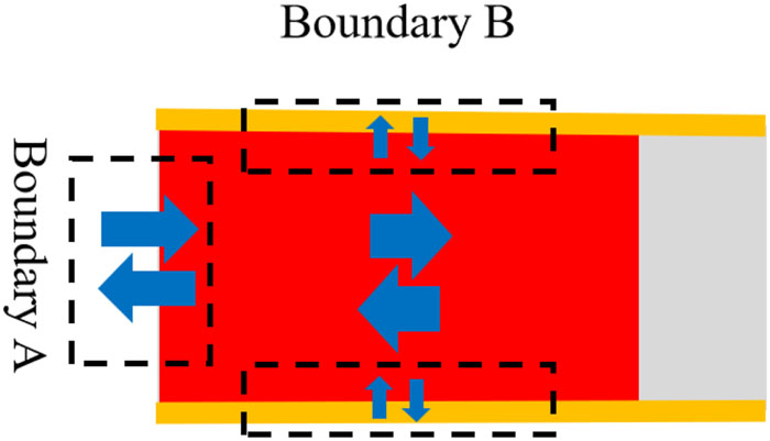
When the low-Z foam cylinder coated by the high-Z wall is irradiated by x-rays, Marshak waves propagate both in the low-Z foam and in the high-Z wall. Under the assumption that the cylinder is semi-infinite in length, the boundary conditions for the Marshak wave in the filled foam are as shown in Fig. 1, where boundary A corresponds to the source surface and boundary B to the interface between low-Z and high-Z materials.
![]()
Figure 1.Energy transport of a two-dimensional Marshak wave. Boundary A corresponds to the source surface and boundary B to the interface between the low-Z and high-Z materials. The red and gray regions are the heated and unheated low-Z foam, respectively. The yellow region is the high-Z material.
In the present work, the two-dimensional Marshak wave is investigated from an energy perspective. The behavior of the energy transport is shown in Fig. 1. To represent this behavior in a simple way, the energy transport is divided into that in the axial direction and that in the radial direction. The drive source is at boundary A, and the net energy flux causes energy to be deposited in the low-Z foam or to be lost to vacuum. The high-Z wall is at boundary B, where the net energy flux causes energy to be lost to the high-Z material. The energy loss to the wall plays an important role in the behavior of the two-dimensional Marshak wave and is taken here to be key to interpreting this behavior.
Given the similarity of the energy transport at boundaries A and B, the energy loss to the high-Z wall at boundary B is taken into account in our model via an alternative approach, with this loss being subtracted from the drive source and the wall loss is ignored. Then, once the energy loss has been estimated, the two-dimensional Marshak wave can be analyzed using familiar one-dimensional theoretical tools in a plane geometry.
A. One-dimensional theory of Marshak waves
One-dimensional Marshak waves have been extensively investigated, and self-similar solutions have been obtained for various boundary conditions.1,10–13,15–17 Using a perturbation technique, Hammer and Rosen11 obtained solutions of the following one-dimensional radiation transport equation under the diffusion approximation:
With the assumed power-law material properties, and provided that the surface temperature Ts varies smoothly, analytical results can be obtained for the temperature profile and heat front position of a supersonic Marshak wave. These can be expressed as follows:
B. Two-dimensional effect
In our model, the two-dimensional effect is determined by the energy leaking from the low-Z foam to the high-Z wall, which is the key quantity that needs to be calculated. The heated low-Z foam can be regarded as the drive source for the Marshak wave that propagates along the radial direction in the high-Z wall, similar to the Marshak wave that propagates along the axial direction in the low-Z foam. Therefore, the Marshak waves in the low-Z foam and high-Z wall are not independent. The total input energy consists of the energy that is deposited in the low-Z foam and the energy loss to the high-Z wall. In other words, to obtain the energy loss, it is essential to know the total input energy and the relationship between the deposited energy and the energy loss.
1. Total input energy
The total input energy Etotal(t) is determined by the net energy flux F(0, t) at the source surface:
On the other hand, the total input energy for a cylindrical geometry without a lossy wall can be calculated from the internal energy of the heated material:
The total input energy for a cylinder without a lossy wall (i.e., where the wall loss is ignored) can be determined by solving Eqs. (9)–(11). For the cylinder with a lossy wall considered in the present work, the total input energy is approximately the same as that for a cylinder without a lossy wall.
2. Interdependent energies: Energy loss and deposited energy
Even once the total input energy has been obtained, the energy loss to the high-Z wall cannot be estimated until its relationship with the energy that is deposited in the low-Z foam has been determined, and here the fact that the heated foam drives the Marshak wave in the wall provides the link between the two energies.
Figure 2 shows a schematic of the Marshak waves in the cylinder, with the heat front positions of the waves in the low-Z foam and high-Z wall at time t being denoted by
![]()
Figure 2.Schematic of the Marshak waves in the cylinder at time
First, we calculate the energy loss to the high-Z wall. This is determined by the drive source, which in our model is the heated low-Z foam. Here, the energy transport along the Z direction in the high-Z wall is ignored. The energy loss to the high-Z wall at axial position z is estimated via the internal energy of the heated high-Z wall:
Second, we calculate the energy deposited in the low-Z foam. This is affected by the energy loss, which, in our model, as already mentioned, is subtracted from the drive source and the wall loss is ignored. Using this approach, the Marshak wave in the low-Z foam can be described by Eqs. (3) and (4). Since the geometry of the low-Z foam is cylindrical, Eq. (11) can be applied to estimate the energy deposited in the low-Z foam:
Finally, the equation
To conclude, at each time step, the total input energy Etotal(t) is obtained first via Eq. (11). Then, H′(t) in Eq. (14) is obtained via Eq. (15), thus determining the heat front position in the low-Z foam, the energy loss, and the deposied energy. In this way, the behavior of the two-dimensional Marshak wave can be described.
III. NUMERICAL RESULTS AND DISCUSSION
In the present work, we focus on processes relevant to ICF and therefore consider typical ICF conditions. The drive temperature is taken to be 100–300 eV, with the corresponding radiation energy directly imposed on the source surface. The density of the low-Z foam is taken to be 0.01–0.15 g/cm3. Explicitly, the propagation of the two-dimensional Marshak wave in a 0.05 g/cm3 SiO2 cylinder that is coated by 19.3 g/cm3 Au is investigated, where the cylinder is driven by a 150 eV thermal bath. For the low-Z foam SiO2, the material parameters defined in Eqs. (3) and (4) are39
The radius of the cylinder is 0.086 cm, corresponding to one free path of the filled foam with ρ = 0.05 g/cm3 and T = 150 eV, and the thickness of the Au wall is 0.001 cm.
A. Two-dimensional Marshak waves with and without a lossy wall
With the help of the MULTI2D code,26,27 we carry out a validation of our proposed method describing the effect of the energy loss, in which this loss is subtracted from the drive source and the wall loss is ignored, as a consequence of which the energy deposited in the low-Z foam remains unchanged. In the simulations, we assume one-frequency-group radiation transport along rays in three dimensions, with the 4π solid angle discretized in direction.
First, the process described above is simulated using the MULTI2D code for the case with a lossy wall, and the results for the heat front position xF are shown in Fig. 3 by the black dashed curve. The heat front position is taken to be the position at which the temperature drops to zero, and the radial position is taken to be that at which the radius is half that of the low-Z foam cylinder. Figure 4 shows the simulation result for the energy deposited in the low-Z foam per unit cross-sectional area of the foam cylinder,
![]()
Figure 3.Heat front position
![]()
Figure 4.Simulation results for the energy deposited in the low-Z foam per unit cross-sectional area of the foam cylinder,
Second, the corresponding process without a lossy wall is simulated using the MULTI2D code, with the energy loss to the wall in the previous simulation now being subtracted from the drive source instead. This situation corresponds to an SiO2 cylinder of infinite radius coated by Au of thickness 0.001 cm and irradiated by the reduced drive source. From the
![]()
Figure 5.Effective drive temperature for the process without a lossy wall. With this drive source, the
It can be seen that the two curves in Fig. 3 are close, which indicates that our method for describing the two-dimensional effect is a reasonable one.
Before presenting the numerical results of our model, we investigate the error due to the theoretical tools employed, which is one of two sources of modeling error, the other being the modeling scheme. The solutions obtained by Hammer and Rosen11 have proved to be very useful, but they do cause errors in optically thin regions because of the adoption of the diffusion approximation in their derivation.
In Fig. 6, the divergence between the Hammer–Rosen solutions and the simulations is presented, where the simulation conditions are as follows: TDrive = 150 eV, the SiO2 material parameters are those in Eq. (16), and the radius of the SiO2 cylinder is 4.0 cm, which can be considered to be infinite compared with the free path of SiO2. Here, we redefine the optical depth as
![]()
Figure 6.Error due to the Hammer–Rosen solutions. Here,
As the Marshak wave propagates, the error due to the diffusion approximation becomes negligible, being less than 15% for τ′ ≥ 1 and dropping to ∼5% for τ′ = 3. Therefore, it is expected that the results estimated using the model and the MULTI2D results will be comparable once the Marshak wave has propagated at least one free path. In other words, our model can be considered to be reliable when the thickness of the heated material is greater than one free path.
B. Energy loss, deposited energy, and heat front position from model and simulation
The key step in the proposed model is the estimation of the energy loss to the high-Z wall, which is also an important quantity for the two-dimensional Marshak wave. In addition, the deposited energy and the heat front position in the low-Z foam are critical for the two-dimensional process. All three of these quantities are estimated in our model, and to validate the model, relevant simulations are also performed.
1. Constant drive temperature
For the process described in Sec. III A with a constant drive temperature T = 150 eV, our model is applied to estimate the energy loss, the deposited energy, and the heat front position, with the results shown in Fig. 7 (red solid curves), together with those of the simulations (black dashed curves). It can be seen that the energy loss predicted by our model is smaller than that from the simulation. For the heat front position, our model predicts a faster Marshak wave than the simulation. Meanwhile, corresponding to the larger value of the heat front position, the deposited energy predicted by the model is also larger. As we have mentioned above, the energy loss is the primary two-dimensional effect slowing down the Marshak wave, and it is thus natural that the estimated smaller energy loss leads to a larger value of the heat front position, where the diffusion approximation, as shown in Fig. 6, also has an effect. For the results at t = 10 ns, the errors in the energy loss, the deposited energy, and the heat front position are ∼15%, ∼2%, and ∼6%, respectively.
![]()
Figure 7.Numerical results in the case of a constant drive temperature for (a) energy loss
2. Time-dependent drive temperature
In experiments, a time-dependent drive temperature is usually employed. Therefore, the process in which a cylinder with sleeve irradiated by a time-dependent radiation source is now considered, with the filled material and the coated material again being 0.05 g/cm3 SiO2 and 19.3 g/cm3 Au, respectively. The corresponding material parameters are given in Eqs. (16) and (17). The radius of the cylinder is 0.08 cm, the thickness of the sleeve is 0.0025 cm, and the time-dependent drive temperature is that shown in Fig. 8. The corresponding experiments were carried out by Back et al.34 at the Omega laser facility at the Laboratory for Laser Energetics, where a 2.4 ns long laser pulse was applied to heat a hohlraum with ∼10 kJ of 0.35 mm laser light. The length and diameter of the hohlraum were 1.2 and 1.6 mm, respectively, and there was only one laser entrance hole, with diameter 1.2 mm.
![]()
Figure 8.Time-dependent drive temperature, which first increases and then decreases.
The energy loss, the deposited energy, and the heat front position were estimated using our model, and the results are presented in Fig. 9 (red solid curves), together with the simulation results (blue dotted curves). Compared with the simulation results, the energy loss estimated by the model is slightly smaller, while the deposited energy is larger, causing a faster Marshak wave. Nevertheless, the results from the model and the simulation can be regarded as consistent, which is similar to the case of a constant drive temperature TDrive = 150 eV. It is found that the errors here (e.g., 17% in the heat front position) are larger than those in Fig. 7 at t = 10 ns, the reason being that the transported distance of the Marshak wave in the low-Z foam is much smaller than the mean free path of the foam.
![]()
Figure 9.Numerical results in the case of a time-dependent drive temperature for (a) energy loss
3. Different cylinder sizes and foams
Besides the drive temperature, the behavior of the two-dimensional Marshak wave in a cylinder with sleeve also depends on the radius of the cylinder and the type of foam. To validate our model, two more processes similar to that in Sec. III B 1 but with different cylinder radius and filling material are considered. The cylinder radius is changed to R = 0.043 cm. As filling material, the 0.05 g/cm3 SiO2 is replaced by 0.15 g/cm3 CH. The material parameters for the CH are39
In Table I, we present the numerical results for the energy loss, the deposited energy, and the heat front position from both the model and simulations. The time chosen is that at which the Marshak wave has propagated one free path, because the model results can be considered reliable from that moment onward. It can be seen that the results of the model are in agreement with those of the simulation.
| EWall (kJ) | EFoam (kJ) | xF (cm) | ||||
|---|---|---|---|---|---|---|
| Process (MFoam, TDrive, ρ, R) | Model | Simulation | Model | Simulation | Model | Simulation |
| I (SiO2, 150, 0.05, 0.043) | 0.355 | 0.440 | 0.737 | 0.706 | 0.195 | 0.175 |
| II (CH, 150, 0.15, 0.034) | 0.0963 | 0.110 | 0.924 | 0.844 | 0.0600 | 0.0547 |
Table 1. Numerical results of the energy loss EWall, the deposited energy EFoam and the heat front position xF. The parameters in the square bracket are the material of the filled low-Z foam MFoam, the drive temperature TDrive (eV), the density of the filled foam ρ (g/cm3), and the radius of the foam cylinder R (cm).
4. Comparison with a different model
For the process with time-dependent drive temperature considered in Sec. III B 2, the energy loss, the deposited energy, and the heat front position were also estimated in Ref. 38 using a different theoretical model, the results of which are also shown in Fig. 9 (black dashed curves). It can be seen that for both the model in Ref. 38 and our model, the results for the deposited energy [Fig. 9(b)] and the heat front position [Fig. 9(c)] fit the simulation results well. However, there is a significant divergence in the results for the energy loss between the model in Ref. 38 and the simulation. The results for the energy loss from our model, however, still show a good fit with the simulation results. In particular, at t = 2.5 ns, the energy losses according to our model and the simulation are very similar, 0.421 kJ and 0.423 kJ, respectively, whereas the energy loss according to the model in Ref. 38 is ∼1.92 kJ. Our model provides a better description of the experiments compared with the model in Ref. 38 because of the different way describing the energy loss to the wall: in Ref. 38, a greater energy loss was obtained, since it was not estimated self-consistently via a slowed 2D Marshak wave depending on this energy loss. It should also be stressed here that Marshak waves in the case of a cylinder with smaller radius depend more strongly on the energy loss.
C. Discussion
Our model, which provides a good description of a two-dimensional Marshak wave, has been validated by simulation results for a number of processes. Owing to the use of the diffusion approximation, there is a deviation between the results of our model and those of simulations in the early stage, but as the Marshak wave propagates, this deviation decreases. The results obtained using the model indicate that the behavior of a Marshak wave with or without a lossy wall depends mainly on the deposited energy and that the energies in the case of a low-Z foam and a high-Z wall can be approximately estimated from those for processes without a lossy wall.
Our model provides a much better description of a two-dimensional heat wave than the solutions obtained without the energy loss effect. Calculations with our model are also more efficient than simulations. Although the present model is for a cylinder with sleeve, it could be extended to more complicated geometries. In addition, for specific problems, the Hammer–Rosen solutions could be replaced by other solutions, and the model should still work.
IV. SUMMARY
In the present work, two-dimensional Marshak waves in a cylinder filled with low-Z foam and with a sleeve made of high-Z material have been studied. Two-dimensional Marshak waves behave differently from one-dimensional Marshak waves owing to the presence of an additional boundary, and current theories are incomplete. An important experimentally observed phenomenon in the case of two-dimensional Marshak waves is their slower propagation compared with one-dimensional Marshak waves.
To explain the slowing of two-dimensional Marshak waves, as well as the associated energy transport, a semi-analytical model has been constructed under the assumption that the primary two-dimensional effect is the loss of energy to the high-Z wall. In the model, the effect of this energy loss is included in an indirect way, in which the energy loss is subtracted from the drive source and the wall loss is ignored. It is then possible to investigate the two-dimensional process using the familiar one-dimensional theory in a planar geometry. Calculation of the energy loss is a crucial task and is performed taking account of the interdependence of this energy loss and the deposited energy. Using this approach, the energy loss, the deposited energy, and the heat front position are determined.
The model has been employed to investigate two-dimensional Marshak waves under typical ICF conditions, and the processes involved have also been simulated by the MULTI code to validate the model. For a given energy of the region heated by the Marshak waves, it is found that these waves behave similarly for processes with and without a lossy wall. It is also found that the results from the model and simulations are consistent when the Marshak waves propagate more than one free path. Calculations using the model are more efficient than simulations, and the model can be regarded as an additional tool for investigating two-dimensional Marshak waves. With the development of numerical simulations of two-dimensional radiation transport, further theoretical investigations are desirable, and we hope that better understanding of radiation transport can be achieved in the future, providing support for studies of ICF physics.
ACKNOWLEDGMENTS
Acknowledgment. C.-J.X. would like to thank Chuang Xue for useful discussions and Wu Wen for debugging of the MULTI code. This work is supported by the State Key Laboratory of Laser Interaction with Matter under Grant No. SKLLIM2108 and by the China Postdoctoral Science Foundation under Grant No. 2021M690468.
References
[1] R. E.Marshak. Effect of radiation on shock wave behavior. Phys. Fluids, 1, 24(1958).
[2] Y. P.Raizer, Y. B.Zeldovich. Physics of Shock Waves and High Temperature Hydrodynamics Phenomena(1984).
[3] M. D.Rosen. The science applications of the high-energy density plasmas created on the Nova laser. Phys. Plasmas, 3, 1803(1996).
[4] D.Arnett, H.Drake, R.Paul, B. A.Remington, H.Takabe. Modeling astrophysical phenomena in the laboratory with intense lasers. Science, 284, 1488(1999).
[5] P.Amendt, R. L.Berger, S. G.Glendinning, S. H.Glenzer, S. W.Haan, R. L.Kauffman, O. L.Landen, J. D.Lindl, L. J.Suter. The physics basis for ignition using indirect-drive targets on the national ignition facility. Phys. Plasmas, 11, 339(2004).
[6] B.Albertazzi, P.Mabey, T.Michelet?al.. Laboratory observation of radiative shock deceleration and application to SN 1987A. Astrophys. J., 888, 25(2020).
[7] T. M.Guymer, A. S.Moore, J.Mortonet?al.. Characterization of supersonic radiation diffusion waves. J. Quant. Spectrosc. Radiat. Transfer, 159, 19(2015).
[8] M.Koenig, T.Michel, R.Yurchaket?al.. Interaction of a highly radiative shock with a solid obstacle. Phys. Plasmas, 24, 082707(2017).
[9] N.Charpentier, A.Ciardi, é.Falize, V.Tranchant, L.Van Box Som. New class of laboratory astrophysics experiments: Application to radiative accretion processes around neutron stars. Astrophys. J., 936, 14(2022).
[10] R.Pakula, R.Sigel. Self-similar expansion of dense matter due to heat transfer by nonlinear conduction. Phys. Fluids, 28, 232(1985).
[11] J. H.Hammer, M. D.Rosen. A consistent approach to solving the radiation diffusion equation. Phys. Plasmas, 10, 1829(2003).
[12] N.Kaiser, J.Meyer-ter-Vehn, R.Sigel. The X-ray-driven heating wave. Phys. Fluids B, 1, 1747(1989).
[13] J. H.Hammer, M. D.Rosen. Analytic expressions for optimal inertial-confinement-fusion hohlraum wall density and wall loss. Phys. Rev. E, 72, 056403(2005).
[14] J. H.Hammer, O. A.Hurricane. Bent Marshak waves. Phys. Plasmas, 13, 113303(2006).
[15] C.Cherfils-Cléerouin, J.Garnier, G.Malinié, Y.Saillard. Self-similar solutions for a nonlinear radiation diffusion equation. Phys. Plasmas, 13, 092703(2006).
[16] P.Arnault, Y.Saillard, V.Silvert. Principles of the radiative ablation modeling. Phys. Plasmas, 17, 123302(2010).
[17] S. I.Heizler, T.Shussman. Full self-similar solutions of the subsonic radiative heat equations. Phys. Plasmas, 22, 082109(2015).
[18] J.Li, G.Meng, M.Wang, J.Yang, W.Zhang, T.Zhu, S.Zou. A simple method to verify the opacity and equation of state of high-Z plasmas. Phys. Plasmas, 20, 092704(2013).
[19] J.Li, G.Meng, J.Wang, X.Wang, W.Zhang. Generation of a sharp density increase in radiation transport between high-Z and low-Z plasmas. Matter Radiat. Extremes, 1, 249(2016).
[20] G.Meng, M.Wang, S.Zou. The theoretical investigation of radiation transport in a slot. Phys. Plasmas, 26, 022708(2019).
[21] Z.Liu, G.Meng, Y.Zhao. A theoretical criterion for the closure of slots filled with low-Z foam. Phys. Plasmas, 27, 033303(2020).
[22] G.Meng, J.She, T.Song, M.Wang, J.Yang. Theoretical investigations on x-ray transport in radiation transport experiments on the Shenguang-III prototype laser facility. Matter Radiat. Extremes, 7, 025901(2022).
[23] T.Feng. A numerical method for solving radiation transport equation on Lagrangian mesh. Chin. J. Comput. Phys., 21, 427(2004).
[24] W. L.Kruer, G. B.Zimmerman. Numerical simulation of laser-initiated fusion. Comments Plasma Phys. Controlled Fusion, 2, 51(1975).
[25] T. R.Dittrich, N. A.Gentile, S. W.Haan, O.Jones, G. D.Kerbel, M. M.Marinak, D.Munro, S.Pollaine. Three-dimensional HYDRA simulations of national ignition facility targets. Phys. Plasmas, 8, 2275(2001).
[26] J.Meyer-ter-Vehn, R.Ramis, J.Ramrez. MULTI2D-a computer code for two-dimensional radiation hydrodynamics. Comput. Phys. Comm., 180, 977(2009).
[27] K.Eidmann, S.Hüller, J.Meyer-ter-Vehn, R.Ramis. MULTI-fs-A computer code for laser-plasma interaction in the femtosecond regime. Comput. Phys. Comm., 183, 637(2012).
[28] L.Dongxian, L.Jinghong, S.Kexu, J.Shaoen, Z.Wenhai, H.Xin, X.Yan, H.Yixiang, D.Yongkun, Z.Zhijian. Supersonic propagation of heat waves in low density heavy material. Plasma Sci. Technology, 7, 2965(2005).
[29] T.Chang, Y.Ding, T.Feng, S.Jiang, D.Lai, K.Lan, S.Li, W.Pei, Y.Xu. Two-photon group radiation transfer study in low-density foam cylinder. Laser Part. Beams, 24, 495(2006).
[30] Y.Guo-Hong, Y.Jia-Min, Z.Ji-Yan, J.Shao-En, H.Xin, D.Yao-Nan, H.Yi-Xiang, L.Yong-Sheng. Experimental observation of ionization and shock fronts in foam targets driven by thermal radiation. Chin. Phys. B, 19, 025201(2010).
[31] Y.Ding, Y.Ding, X.He, Z.Hu, J.Li, S.Liu, G.Meng, Y.Xu, J.Yang, R.Yi, J.Zhang, T.Zhu. Experimental study of the hydrodynamic trajectory of an x-ray-heated gold plasmas. Phys. Plasmas, 17, 062702(2010).
[32] Z.Dai, F.Ge, T.Huang, W.Jiang, C.Li, X.Li, C.Wu, P.Yang, W.Zheng, S.Zou. Investigations on the hohlraum radiation in the first shaped laser pulse implosion experiment at the SGIII laser facility. Phys. Plasmas, 26, 022705(2019).
[33] J.Edwards, D.Hoarty, A.Iwase, C.Meyer, O.Willi. Characterization of laser driven shocks in low density foam targets. Phys. Rev. Lett., 78, 3322(1997).
[34] C. A.Back, J. D.Bauer, J. H.Hammer, W. W.Hsing, O. L.Landen, B. F.Lasinski, P. W.Rambo, M. D.Rosen, L. J.Suter, R. E.Turner. Diffusive, supersonic x-ray transport in radiatively heated foam cylinders. Phys. Plasmas, 7, 2126(2000).
[35] C. A.Back, J. D.Bauer, J. H.Hammer, W. H.Hsing, O. L.Landen, B. F.Lasinski, M. D.Rosen, L. J.Suter, R. E.Turner. Detailed measurements of a diffusive supersonic wave in a radiatively heated foam. Phys. Rev. Lett., 84, 274(2000).
[36] C. A.Back, K.Baker, J.Castor, A. J.Comley, A. B. R.Cooper, J.Foster, G.Glendinning, P.Graham, W. W.Hsing, J.Hund, J.Klingmann, K.Lu, S.MacLaren, R.Marrs, M.May, A. S.Moore, J.Sain, J.Satcher, M. B.Schneider, R.Seugling, K.Widmann, B.Young, P.Young. Radiation transport and energetics of laser-driven half-hohlraums at the National Ignition Facility. Phys. Plasmas, 21, 063303(2014).
[37] S.Allan, N.Bazin, J.Benstead, C.Bentley, A. J.Comley, J.Cowan, K.Flippo, W.Garbett, T. M.Guymer, C.Hamilton, J. L.Kline, N. E.Lanier, A. S.Moore, J.Morton, K.Mussack, K.Obrey, L.Reed, D. W.Schmidt, R. M.Stevenson, J. M.Taccetti, J.Workman. Quantifying equation-of-state and opacity errors using integrated supersonic diffusive radiation flow experiments on the National Ignition Facility. Phys. Plasmas, 22, 043303(2015).
[38] A. P.Cohen, S. I.Heizler. Modeling of supersonic radiative Marshak waves using simple models and advanced simulations. J. Comput. Theor. Transp., 47, 378(2018).
[39] A. P.Cohen, S. I.Heizler, G.Malamud. Key to understanding supersonic radiative Marshak waves using simple models and advanced simulations. Phys. Rev. Res., 2, 023007(2020).
[40] Y.Jia-Min, S.Tian-Ming. One-dimensional simulation of radiation transport in three-dimensional cylinder. Acta Phys. Sin., 62, 015210(2013).
[41] L. H.Auer, M. L.Hall, G. L.Olson. Diffusion,
[42] M.Guang-Wei, L.Jing-Hong, L.Shuang-Gui, Z.Wei-Yan, P.Wen-Bing. Effect of temperature gradient on the non-equilibrium rate of flux emitted by plane gold wall. Acta Phys. Sin., 60, 025210(2011).


Set citation alerts for the article
Please enter your email address

© Copyright 2018-2021 | Chinese Laser Press. All Rights Reserved 沪ICP备15018463号-20