A beam combination setup for a dual-frequency laser with orthogonal linear polarization is proposed. It consists of two polarizing beam splitters (PBSs) whose polarization axes are orthogonal to each other. A theoretical analysis demonstrates that a combined dual-frequency laser beam with this setup strictly meets orthogonal linear relation. The experimental results show that compared with the conventional setup, the ellipticity and nonorthogonality of the combined dual-frequency laser beam are significantly reduced.
Heterodyne laser interferometry is widely applied in precision metrology and manufacturing[1–5] due to its advantages of a high measurement accuracy, excellent signal-to-noise ratio, and direct traceability to the length standard. A core component of a heterodyne laser interferometer is the dual-frequency laser source whose specifications restrict the measurement velocity and accuracy of the interferometer. The frequency difference of the laser source determines the maximum measurement speed, and the polarization state of the laser source limits the accuracy because it is a primary factor leading to periodic error[6,7], i.e., the optical nonlinearity. Generally, orthogonal linear polarization is required. In order to pursue a higher measurement speed, acousto-optic modulation technology is often adopted in the fabrication of dual-frequency laser sources with a large frequency difference[8–10], where the laser beam is divided into two parts that are recombined to one coaxial beam after their frequencies are modulated. Therefore, a setup for beam combination is necessary. Usually, a single polarizing beam splitter (PBS) plays this role[8,11]. However, in actual experiments, it was found that the combined dual-frequency laser beam with a single PBS might apparently deviate from linear orthogonality, which subsequently results in considerable optical nonlinearity.
In this Letter, the problem of the conventional setup with a single PBS is discussed. Then, an improved setup that includes two PBSs is presented. A theoretical analysis and experiments are carried out to verify the feasibility of this setup.
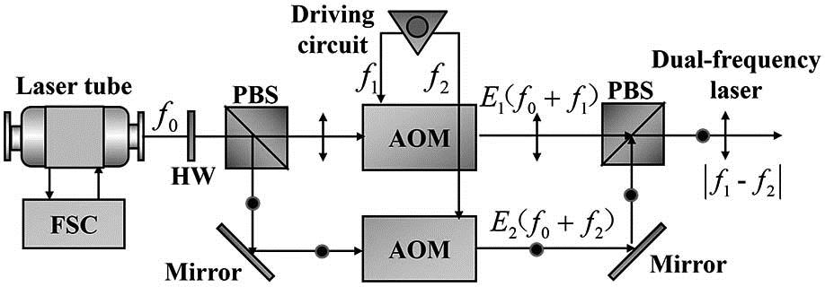
Figure 1 shows a schematic diagram of a typical dual-frequency laser source based on acousto-optic modulation technology. The frequency-stabilized laser tube outputs a single-frequency (denoted as ) laser beam whose polarizing direction can be rotated by a wave plate. A PBS divides the laser into two linearly polarized beams: one beam passes through an acousto-optic modulator (AOM) and its optical frequency is shifted by , while the other beam passes through another AOM and its frequency is shifted by . Another PBS recombines these two beams into one dual-frequency laser beam with orthogonal linear polarization, and the frequency difference is , which can be conveniently adjusted by changing the driving frequencies of the two AOMs.
Sign up for Chinese Optics Letters TOC. Get the latest issue of Chinese Optics Letters delivered right to you!Sign up now
Figure 1.Schematic diagram of a typical dual-frequency laser source based on acousto-optic modulation technology. FSC, frequency stabilization circuit; HW, half-wave plate.
In an ideal case, the two incident laser beams of the second PBS in Fig. 1 are linearly polarized. The polarizing direction of one beam is parallel to the horizontal plane (the paper plane), i.e., the beam, while the polarizing direction of the other beam is perpendicular to the horizontal plane, i.e., the beam. The incident angles of the and beams in the diagonal plane (coated with polarizing film) of the PBS are both the Brewster angle (designed as 45°). Therefore, the beam passes through the PBS, and the beam is totally reflected by the PBS. If their incident points in the diagonal plane are identical, then the two beams can be recombined into a coaxial beam with orthogonal linear polarization, which is expected by a heterodyne laser interferometer.
In a practical case, it is found that both the mirrors (coated with aluminum) and the AOMs in Fig. 1 can affect the laser polarization. Therefore, the two incident beams of the PBS are not completely linearly polarized. In addition, to obtain a coaxial beam with orthogonal linear polarization, the incident points of the two beams in the diagonal plane of the PBS must be identical. Moreover, the incident angles of both the two beams in diagonal plane of the PBS should be kept exactly at the Brewster angle. However, in a real situation, it is difficult to satisfy these conditions simultaneously, and the polarization state of the combined dual-frequency laser might be significantly different from that of an ideal case.
In order to describe the above problem, it is first necessary to analyze the optical characteristics of a PBS. The polarizing film coated in the diagonal plane consists of medium layers with alternating high and low refractive indices, i.e., the film system. The structure of a typical film system can be expressed as G(HL)nHG, where G, H, and L represent the glass, the medium layer with a high refractive index, and the medium layer with a low refractive index, respectively, and is a positive integer indicating the number of the layers. The reflectivities of the and beams can be calculated using the optical effective admittance method[12], given by where , , and are the refractive indices of the glass, the H layer, and the L layer, respectively. , , and are the incident angles in the glass, the H layer and the L layer, respectively. The relation of these three angles follows the refraction law, given by
Figure 2 shows the reflectivity curves of the and beams when , , , and , where the horizontal axis is the incident angle . It can be seen from Fig. 2 that the reflectivity of the beam is always kept at 1.0 as a variation of the incident angle, which means that the beam is totally reflected by the PBS even when the incident angle apparently deviates from the Brewster angle (45°). However, the reflectivity of the beam increases rapidly from zero as the incident angle deviates from the Brewster angle.
When the two incident laser beams of the second PBS in Fig. 1 are not linearly polarized, they can be decomposed into two orthogonal components, as shown in Fig. 3. The incident laser beam is decomposed into and , and the incident laser beam is decomposed into and . Generally, and . If (with frequency ) denotes the laser beam after passes through the PBS, and (with frequency ) denotes the laser beam after is reflected by the PBS ( and together form a dual-frequency laser beam), their expressions can be deduced as follows: where and are the incident angles of and in the diagonal plane of the PBS respectively, and , which can be directly obtained from Fig. 2. In a considerable range around the Brewster angle, the reflectivity of the beam is 1. As shown by Eqs. (4) and (5), only contains the component, but contains both the and components. The dot product of and is given by
When the incident beams and are not linearly polarized , and according to Fig. 2, . Therefore, Eq. (6) is not zero unless , and, as shown in Fig. 2, this requires that is exactly equal to the Brewster angle. However, as mentioned above, to obtain a coaxial dual-frequency laser beam, this condition cannot be always satisfied, and Eq. (6) might not be zero. This means that the combined dual-frequency laser beam does not meet the orthogonal linear relation, and this will lead to a serious optical nonlinearity when the dual-frequency laser beam is applied in heterodyne interferometry.
In order to solve the above problem, an improved beam combination setup for a dual-frequency laser is proposed. As shown in Fig. 4, the setup consists of two PBSs (PBS1 and PBS2), which are glued together by optical cement. The polarization axes of the two PBSs are orthogonal to each other; in other words, the axis of PBS1 is perpendicular to the axis of PBS2, and the axis of PBS1 is perpendicular to the axis of PBS2. Because of the special configuration, is the beam for PBS1, but it is the beam for PBS2. is the beam for PBS1, but it is the beam for PBS2. The output laser beams and of this setup can be deduced as follows: where is the incident angle of in the diagonal plane of PBS1, is the incident angle of in the diagonal plane of PBS2, and is the incident angle of in the diagonal plane of PBS1 after it passes through PBS2. Equation (7) is identical to Eq. (4), and only contains the component with horizontal linear polarization. The major distinction between Eq. (8) and Eq. (5) is that in Eq. (8), the component of is eliminated, because is the beam for PBS2, and according to Fig. 2, . Therefore, is completely reflected by PBS2. For the proposed setup, the dot products of and are given by
Equation (9) shows that the dot product of and always equals zero, which indicates that the combined dual-frequency laser strictly meets the orthogonal linear relation. In addition, Eq. (9) does not require the incident angles and to be exactly equal to the Brewster angle, and this can greatly reduce the difficulty of beam combination.
Figure 4.Beam combination with two orthogonal PBSs.
To verify the effectiveness of the proposed setup, comparison experiments between the conventional setup and the improved setup are carried out, and the polarization parameters of the combined dual-frequency laser beam are measured, as shown in Fig. 5, including the ellipticity angles and , and the nonorthogonality angle . Figure 6 shows the experimental system for the polarization measurement of a dual-frequency laser beam. The combined dual-frequency laser beam directly passes through a polarizer (a Glan-Thompson prism with a extinction ratio up to ) to form an optical beat signal, and a photo detector converts the beat signal to an electrical signal, whose amplitude is measured by the detection circuit of the signal amplitude. The polarizer is mounted on a precision rotatory apparatus driven by a stepper motor, and the signal amplitude can be recorded with the variation of the polarizer azimuth, i.e., the angle in Fig. 5.
Figure 5.Polarization state of a dual-frequency laser beam.
It has been reported in Ref. [13] that the beat signal amplitude of the dual-frequency laser is a periodic function of the polarizer azimuth with a cycle of , and the polarization parameters of the dual-frequency laser can be calculated with the peaks and valleys in one cycle. Figures 7(a) and 7(b) show the normalized beat signal amplitude in two cycles for the conventional setup and the improved setup, respectively. In each cycle there are two different peaks (denoted as and ) and two different valleys (denoted as and ). By substituting these four values into Eqs. (14) and (15) in Ref. [13], the ellipticity angles and and the nonorthogonality angle can be determined.
Figure 7.Normalized beat amplitude for (a) the conventional setup and (b) the improved setup.
Tables 1 and 2 show the peaks and valleys of the beat signal amplitude in five continuous cycles for the conventional setup and the improved setup, respectively, where the amplitude is normalized by the maximum peak, and the calculated polarization parameters are also presented. The average values of , , and in Table 1 are 0.157°, 2.202°, and 1.210°, respectively. Therefore, for the combined dual-frequency laser beam with the conventional setup, one of the ellipticity angles is significantly greater than the other; moreover, the considerable value of indicates that the combined dual-frequency laser beam obviously deviates from orthogonality. These experimental results are consistent with the theoretical results of Eqs. (4), (5), and (6). The average values of , , and in Table 2 are 0.154°, 0.146°, and 0.110°, respectively. When compared to the results of the conventional setup, the ellipticity and nonorthogonality are largely reduced. In consideration of a practical situation, the results are in good agreement with the theoretical prediction of Eqs. (7), (8), and (9). For a commercial dual-frequency Zeeman laser source, the typical values of the ellipticity angles and the orthogonality angle are all about 0.5°. Therefore, the combined dual-frequency laser beam with the proposed setup can ably meet the requirement for the polarization state in heterodyne laser interferometry.
P1
V1
P2
V2
ρ1/deg
ρ2/deg
β/deg
0.9990
0.0055
0.9527
0.0791
0.162
2.325
1.362
0.9970
0.0047
0.9630
0.0668
0.137
1.954
0.995
0.9980
0.0050
0.9626
0.0799
0.146
2.338
1.036
1.0000
0.0063
0.9483
0.0821
0.185
2.417
1.522
0.9990
0.0053
0.9602
0.0675
0.155
1.976
1.136
Table 1. Extreme Values of Beat Amplitude and the Calculated Polarization Parameters (for conventional setup)
As mentioned above, the polarization axes of the two PBSs in Fig. 4 are orthogonal to each other. This is crucial for the proposed setup: if this condition is not met, the performance of the proposed setup is similar to that of the conventional setup with a single PBS. In this case, the transmission laser of PBS2 is not purely the beam for PBS1, and according to Fig. 2, if its incident angle in the diagonal plane of PBS1 is not exactly the Brewster angle, a portion of the component of the transmission light of PBS2 is also reflected by PBS1, which will undoubtedly deteriorate the polarization state of the combined dual-frequency laser beam. For the proposed setup, before the two PBSs are glued together, their polarizing axes are adjusted to be orthogonal to each other throughout the experiments. PBS1 in Fig. 4 is mounted on a precision rotary stage driven by a stepper motor (MRS312, angle resolution 0.009°), and its rotation axis coincides with laser beam . With laser beam blocked, the intensity of the transmission laser (from ) of PBS1 is detected by a light power meter (Thorlabs-PM320E, power resolution 1 nW). Figure 8 shows the transmission laser intensity of PBS1 vs. the angle error between the polarizing axes of the two PBSs, where the background light intensity is removed and the angle related to the minimum intensity (about 2 nW) is defined as the zero of the horizontal axis. When the intensity is minimized by rotating PBS1, the polarizing axes of the two PBSs are adjusted to be orthogonal to each other, and then they are kept still and are glued together with optical cement.
Figure 8.Transmission laser intensity of PBS1 vs. angle error between polarizing axes of the two PBSs.
In conclusion, in order to improve the polarization quality of the dual-frequency laser beam in a laser source based on AOM, in this Letter, a beam combination setup for a dual-frequency laser with orthogonal linear polarization is proposed. The setup includes two glued PBSs whose polarization axes are orthogonal to each other. A theoretical analysis demonstrates that the combined dual-frequency laser with this setup strictly meets the orthogonal linear relation. The experimental results show that compared with the conventional setup, the ellipticity and nonorthogonality of the combined dual-frequency laser are significantly reduced.