Imaging polarimetry is one of the most widely used analytical technologies for object detection and analysis. To date, most metasurface-based polarimetry techniques are severely limited by narrow operating bandwidths and inevitable crosstalk, leading to detrimental effects on imaging quality and measurement accuracy. Here, we propose a crosstalk-free broadband achromatic full Stokes imaging polarimeter consisting of polarization-sensitive dielectric metalenses, implemented by the principle of polarization-dependent phase optimization. Compared with the single-polarization optimization method, the average crosstalk has been reduced over three times under incident light with arbitrary polarization ranging from 9 μm to 12 μm, which guarantees the measurement of the polarization state more precisely. The experimental results indicate that the designed polarization-sensitive metalenses can effectively eliminate the chromatic aberration with polarization selectivity and negligible crosstalk. The measured average relative errors are 7.08%, 8.62%, 7.15%, and 7.59% at 9.3, 9.6, 10.3, and 10.6 μm, respectively. Simultaneously, the broadband full polarization imaging capability of the device is also verified. This work is expected to have potential applications in wavefront detection, remote sensing, light-field imaging, and so forth.Imaging polarimetry is one of the most widely used analytical technologies for object detection and analysis. To date, most metasurface-based polarimetry techniques are severely limited by narrow operating bandwidths and inevitable crosstalk, leading to detrimental effects on imaging quality and measurement accuracy. Here, we propose a crosstalk-free broadband achromatic full Stokes imaging polarimeter consisting of polarization-sensitive dielectric metalenses, implemented by the principle of polarization-dependent phase optimization. Compared with the single-polarization optimization method, the average crosstalk has been reduced over three times under incident light with arbitrary polarization ranging from 9 μm to 12 μm, which guarantees the measurement of the polarization state more precisely. The experimental results indicate that the designed polarization-sensitive metalenses can effectively eliminate the chromatic aberration with polarization selectivity and negligible crosstalk. The measured average relative errors are 7.08%, 8.62%, 7.15%, and 7.59% at 9.3, 9.6, 10.3, and 10.6 μm, respectively. Simultaneously, the broadband full polarization imaging capability of the device is also verified. This work is expected to have potential applications in wavefront detection, remote sensing, light-field imaging, and so forth.
Introduction
Polarization, an inherent property of the electromagnetic wave, comprises abundant information of substance, which is of profound significance for target detection and identification. As a method for determining the polarization states of the scene, imaging polarimetry plays an indispensable role in polarization information detection, which has been widely adopted in biomedicine1, remote sensing2, and astronomy3. Unlike light intensity and frequency detection, polarimetry is an inherent guardian knot because the phase information between orthogonal polarization states is lost wholly in the conventional detection process. For measuring polarization states in one shot, it is necessary to use beam splitters, waveplates, and polarizers, while the bulk and complexity of the system increase ineluctably4, which is not compatible with the trending desire for integration and miniaturization in optical systems. Consequently, a simple, compact, real-time polarimeter is an urgently needed feature for practical applications.
Inspired by the M-wave assisted law of refraction and reflection, metasurface, as an ultrathin two-dimensional artificial subwavelength material, has powerful capabilities of arbitrary manipulation for amplitude, phase, and polarization5-
8. It provides an ideal platform to overcome the bulky and complex problems in traditional polarimeters benefiting from these capabilities. Recently, metasurfaces have made numerous impressive applications in metalenses, spin-orbit interaction9,
10, and meta-holograms11-
15, facilitating the development of digital optics and catenary optics16,
17. Besides, it has also been considered a preferable candidate for polarization manipulation due to the flexibility of multi-parameter modulation18,
19. The early works achieve polarization detection20 and spectropolarimeter21,
22 by calculating diffraction contrasts of plasmonic metagratings, while the low efficiency caused by the inherent ohmic loss greatly restricts the practical application. Dielectric metasurface with negligible loss provides an attractive platform for high-efficiency devices, which can realize highly efficient polarization-dependent wavefront manipulation23 and polarization multiplexing24,
25. In addition, various dielectric polarimeters are proposed to achieve efficient polarization detection, e.g., ultracompact polarimeters26,
27, Stokes polarization detection28,
29, real-time polarization imaging30,
31, snapshot imaging polarimetry32,
33, Hartmann-Shack wavefront sensor34,
35, and wide-angle polarimetry36. The performance of the polarimeter have been significantly improved, accelerating the development of polarization manipulation technology. Nevertheless, these polarimeters are designed for a single wavelength suffering from large chromatic dispersion, leading to the limited practical applications of polarization technology. There are only several works dedicated to expanding the bandwidth of the polarimeter through metagrating. For instance, Ding et al. propose beam-size invariant spectropolarimeters to simultaneously determine polarization state and wavelength within the scope of 750–950 nm22. Similarly, Tsai et al. report on-chip polarimetry that can determine Stokes parameters in the visible spectrum, which is more compact than commercial ellipsometry37. In addition, Basiri et al. introduce bioinspired chiral metasurfaces working in 1.4–1.55 μm with a relative bandwidth of 0.102 for polarimetric measurements38. Even though considerable headway has been made, these polarimeters are broadband dispersion rather than achromatic broadband devices, which restricts the practical applications to a certain extent. Besides, crosstalk between polarizations is rarely considered, resulting in large errors in practical measurements. Several works, such as ref.34,
35 use the calibration matrix to correct the measurement error, while this method is unsuitable for measuring unknown wavelengths in broadband. Therefore, the efficient control of axial chromatic aberration with reduced crosstalk should be considered to promote the detection capability and imaging performance of the polarimetry within the broadband operating bandwidth.
Metasurfaces also exhibited unrivalled superiority in dispersion control, and numerous efforts have been made in multi-wavelength control39-
41, broadband achromatic42-
48, and enhanced chromatic dispersion49,
50. These metalenses confirm the feasibility of flexible manipulation of chromatic dispersion. However, crosstalk-free broadband achromatic imaging polarimeter has not been demonstrated as far as we know. Therefore, a compact, single shot, crosstalk-free, broadband achromatic polarimeter is essential to promote the desirable quality for detection and imaging. Nearly simultaneously, Feng et al. designed a broadband achromatic metalenses array to achieve broadband polarization detection51. Different from the achromatic metalens, it utilizes the long focal depth of focus to achieve achromatism under circularly polarized incidence, leading to a restricted relative bandwidth for only 0.1678 (1310–1550 nm) and foreseeable unsatisfactory image quality in direct imaging systems. In addition, the experimental results need correction at each wavelength due to relatively high crosstalk, which is difficult for measuring unmeasured wavelengths in practical applications.
In this work, we propose a crosstalk-free imaging polarimeter based on dielectric metasurface in the infrared region ranging from 9 to 12 μm with a relative bandwidth of 0.2857. The broadband achromatic polarimeter consists of 2×3 sub-arrays, each of which acts as a polarizer and achromatic lens. These sub-arrays are elaborately designed through polarization-dependent phase optimization methods and particle swarm optimization (PSO) algorithm. The optimized linear and circular polarization sub-arrays achieve crosstalk-free polarization-sensitive achromatic focusing within the designed bandwidth, numerically and experimentally. Moreover, the designed polarimeter can measure directly and accurately without calibration because crosstalk between orthogonal polarization states is considered in advance to improve the practicality of the device effectively. Finally, polarization imaging performance is demonstrated using a self-built polarization mask carrying polarization information. The device has potential applications in color imaging, anti-counterfeiting, machine vision, atmospheric detection, and vectorial optical field manipulation52.
Principle of crosstalk-free achromatic imaging polarimeter
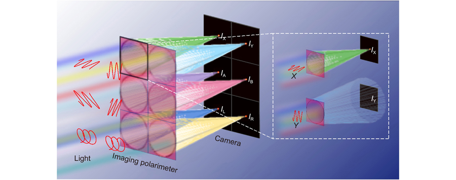
The designed broadband achromatic polarimeter separates arbitrary incident light within the operating bandwidth into different polarization channels and focuses them on a preset focal plane, as depicted in
Fig. 1. The schematic in the white frame on the right shows the principle of polarization-dependent phase optimization, which reduces the effects of crosstalk and thus improves the accuracy of polarimetry. Here, the Stokes vector formalism is employed to represent the polarization of incident light, which is defined as follows:
Figure 1.The schematic of the continuous broadband achromatic imaging polarimeter.The device is composed of 2×3 sub-arrays, each of which can be regarded as an achromatic focusing lens under a specific polarization basis. The focal spots remain at the same plane under different incident lights in 9-12 μm. The schematic in the white frame on the right shows the principle of polarization-dependent phase optimization.
where S0 describes the total intensity of the incident light, S1, S2 and S3 represent the polarization state of the incident light. IX, IY, IA, IB, IL, and IR are the light intensities of the selected basic polarization states, respectively. In order to completely characterize the polarization state of the incident light, six basic polarized lights, namely horizontal (X), vertical (Y), diagonal (A), 90º rotated diagonal (B) linear polarization, and left-handed (L) and right-handed (R) circular polarization., are selected. These polarized light intensities should be measured to characterize the Stokes parameters. In this work, these light intensities at an arbitrary wavelength within the designed bandwidth can be determined on the same focal plane through achromatic metalenses, which indicates absolute superiority compared to the previous metasurface polarimeter with chromatic dispersion.
Subsequently, the design principle of polarimetry can be appropriately divided into the discussion for the design of achromatic metalens. Theoretically, each sub-array in the polarimetry functions as a broadband achromatic polarization-sensitive metalens. The required phase profile for each focusing metalens can be expressed as follows:
where, λ is the working wavelength in free space, f is the preset focal length, and r is the radial distance from an arbitrary position to the center of each metalens. Additional phase shifts φshift(λ) are introduced for the matching database so that we can modify the above phase as:
where φshift(λ) is a reference phase acting as an optimization factor uniquely determined by the wavelength. φ′(r, λ) is linear with λ43.
Equation (3) indicates that the distribution of the focusing phase is highly correlated with the variation of wavelength and reveals that the immanent reason for the chromatic aberration is the different wavevector in the free space propagation. To ensure achromatism, the phase of optimized unit cells should satisfy the phase distribution of φ′(r, λ). Hence the unit cell should possess a smooth and linear phase spectrum. For linear polarization, the phase profile is provided through the transmission phase modulated by changing the geometric parameters of the unit cell. Since polarization detection is affected by crosstalk between orthogonal polarizations, the polarization-dependent phase optimization method is employed to design metalens. The metalens only responds to a specific polarization state while not focusing on its orthogonal polarization to achieve direct full Stokes polarimetry. For simplicity, we set the response of the orthogonal polarization state to the divergent phase, i.e., the opposite of the focusing phase. Therefore, the optimized metalens phase should satisfy two conditions that can be expressed as follows:
Unlike linear polarization, the circularly polarized light achieves broadband achromatism by merging the geometric phase and dynamic phase, which can be divided the above phase into the following forms:
where φ(r, λmax) is dispersionless. It is provided by the geometric phase that originates from photonic spin-orbit interactions and is only related to the rotation angle of the anisotropic nanopillar. Δφ(r, λ) is the phase difference between incident wavelength and λmax supplied by the transmitted cross-polarized phase of nanopillars with different widths and lengths. It is tough to guarantee that the transmissivity of cross-polarization is consistently high. Therefore, the influence of co-polarized outgoing light should be considered in advance. Here, we control the outgoing co-polarization to a divergent phase in the optimization. The optimized phase can be expressed as follows:
The phase of the metalens matches the ideal phase by arranging the corresponding nanopillar appropriately at different r. The polarization-dependent phase optimization method can improve the extinction ratio of the metalens, thereby providing a guarantee for direct and accurate polarization detection without calibration.
In this work, the unit cell is designed with all-dielectric silicon, whose refractive index is 3.42, and the loss can be ignored according to the experimental results measured by the ellipsometer. The silicon nanopillar is arranged at the center of the silicon substrate, which can be considered a waveguide-like cavity41. As shown in
Fig. 2(a), the unit cells with fixed period p=4.3 μm, height h=10 μm, and changeable length l, width w, and spatial orientations θ. For designing broadband achromatic metalenses, databases modulated X- and L-polarization light are established and displayed in
Fig. S1 (Supplementary information). The phase and amplitude responses of unit cells are calculated by the finite element method in CST Microwave Studio. Take the database of X-polarization as an example, the phase responses cover 2π phase space, and sufficient linear phase responses exist in the phase space, which can provide abundant options for chromatic aberrations control, as shown in
Fig. 2(b). For clarity, we present several representative unit cells marked with white pentagrams in
Fig. 2(b).
Figure 2(c) exhibits the amplitude and phase profiles of these unit cells (l1=0.9 μm, w1=1.2 μm, l2=2.8 μm, w2=1.4 μm, l3=2.15 μm, w3=1.8 μm) with phase compensations of 284.24°, 395.93°, and 548.53°. The phase profiles have approximately linear relations with wavelength, which ensures the fantastic realization of the achromatic focusing. The inset shows the normalized magnetic energy density profiles of the unit cell with l1 and w1 at different wavelengths. The magnetic energy is highly concentrated within the dielectric nanopillar, whereas optical coupling among their adjacent nanopillars is extremely feeble because the dielectric nanopillars have a high refractive index compared to the surrounding environment. The low coupling characteristic reveals that the wavefront manipulation is a localized effect, which ensures the accuracy of the simulation. In principle, the responses for Y-polarization and X-polarization are symmetric with the diagonal l = w. Therefore, we only display the responses of unit cells under X-polarization incidence. For circular polarization, the propagation and geometric phase are combined with modulating the phase delay of transmitted light by simultaneously changing the length, width, and spatial orientations (θ) of the silicon nanopillars. The amplitude and cross-polarization phase spectra are displayed in
Fig. S1(b). Different l and w provide various phase compensation for effective achromatic aberration. In summary, the sufficient phase response and relatively high amplitude response guarantee the matching results in optimization for achromatic metalens design.
Figure 2.Optical responses of the unit cells. (a) Schematic illustration of the subwavelength structures. (b) Phase response of the database to X-polarization at discrete sampling wavelengths. (c) The amplitude and phase profiles of the unit cells (l1, w1, l2, w2, l3, w3) are marked with white pentagrams inFig. 2(b). The phase profiles have approximately linear relations with wavelength. The inset is the magnetic energy density profile for the unit cell with l1 and w1 at wavelengths 9, 9.5, 10, 10.5, 11, 11.5, and 12 μm. The black line is the outline of the unit cell. The magnetic energy is strongly concentrated in the dielectric nanopillar.
Taking into account the crosstalk between orthogonal polarizations and fabricating conditions, the achromatic metalenses are designed according to the following optimization conditions: (1) The unit cells within the database meet the fabricating conditions. (2) The phase of the metalens satisfies
Eq. (4) and
Eq. (6) for linear and circular polarization, respectively. (3) The transmissivity of unit cells is as high as possible while satisfying the conditions (1) and (2) to ensure high efficiency. Then, the particle swarm optimization (PSO) algorithm assists us in arranging the unit cells appropriately to follow the required phase from the database42. Eventually, the broadband achromatic metalenses for linear and circular polarization can be obtained. Here, each metalens has a diameter of 1.7243 mm, and the focal length is set as 1 cm. The comparison between the ideal and optimized phases is shown in
Fig. S2 (Supplementary information).
Verification of crosstalk-free performance
To illustrate the superior performance of the polarization-dependent phase optimization method in reducing crosstalk, we compared metalenses designed by the conventional method that considers only a single polarization response with those designed using our method. Two methods are used to design the metalens for X-polarization. That for Y-polarization is transformed from X-polarization. We simulate the X- and Y-polarization-sensitive metalenses numerically under X-polarized incidence. The optical field intensity distributions in the x-z plane, the focal plane, and the cross-sectional z = 0 at 9, 9.3, 9.6, 10.3, 10.6, and 12 μm are calculated by the vector angular spectrum (VAS) theory as shown in
Fig. 3. The simulation results illustrate that no matter which method, the focal lengths are basically maintained at the target focal length f = 1 cm (dashed white line) with almost no deviation under different wavelengths, which is consistent with the theoretical achromatic design. However, our design method is basically crosstalk-free, while the conventional method has significant crosstalk between polarizations. To be more intuitive, we calculate the extinction ratio of the metalens, which is defined as the ratio of the focusing intensity of the metalens with its modulated polarization and its orthogonal polarization. The extinction ratios of linearly polarized metalens designed by our proposed method (marked as Mlinear) and conventional method (marked as Nlinear) at the sampled wavelengths exhibit in
Table 1. The results show that the extinction ratio of our design method is 3.904, 3.926, 4.605, 3.693, 3.494, and 1.820 times higher than that of the conventional method. Similarly, we also analyzed the metalens for circularly polarized light, whose simulation results show in
Fig. S3 (Supplementary information). The extinction ratios of circularly polarized metalens designed by our proposed method (marked as Mcircular) and the conventional method (marked as Ncircular) at the sampled wavelengths show in
Table 2. The average extinction ratio of our design increased 3.57 and 3.06 times under the illumination of linear and circular polarized light ranging from 9 μm to 12 μm compared with the conventional method, respectively, i.e., crosstalk is reduced by more than 66.67%. Our design principle significantly improves the extinction ratio and greatly reduces crosstalk, which guarantees the measurement of the polarization state more precisely.
Figure 3.Simulation results of X- and Y-polarization-sensitive metalenses designed with (a) polarization-dependent optimization method versus (b) conventional design method for X-polarized incident light. The upper diagram shows the intensity distribution in the x-z plane, and the white dashed line is the position of the focal plane. The middle figure is the focal plane intensity profile. The lower part is the normalized intensity profile along the white line.
Table Infomation Is Not EnableTable Infomation Is Not Enable
The achromatic metalenses for Y, A, and B linear polarizations can be easily realized by rotating the nanopillars for X polarization. The achromatic metalens for R circular polarization has an opposite rotation direction to L circular polarization. Therefore, we can compose a polarimeter through metalenses that have been optimized for X- and L-polarization.
Experimental results and discussion
The broadband achromatic polarimeter is fabricated using the process shown in
Fig. 4(a). First, the double-polished silicon wafer cleans according to standard laboratory procedures. Then, 1500-nm-thick photoresist AZ1500 is spin-coated on the pure wafer using a spin coater, after which the designed array pattern is written into the photoresist through a direct laser writing system with a laser wavelength of 405 nm. Next, the photoresist pattern is transferred into the silicon wafer to form a silicon nanopillar array with 10-µm-high employing inductive coupled plasmonic (ICP) etching at a rate of 1 μm/min. Finally, remove the residual photoresist. The scanning electron microscopy (SEM) image of the local of the fabricated polarimeter is given in
Fig. 4(b). To manifest the property of the design imaging polarimeter, broadband performance, polarization detection capability, and imaging capability of the device are probed. The optical setup for the designed polarimetry is exhibited in
Fig. 4(c). The linear polarizers (LP) and a quarter-wave plate (QWP) are used to generate arbitrarily polarized incident beams.
Figure 4.Characterization of the polarimeter. (a) Schematic diagram of the process of fabricating polarimeter. (b) Local SEM image of the polarimeter. The inset is an oblique view of the part of the polarimeter, revealing the high aspect ratio of nanopillars. (c) The optical setup for polarimetry. Optical elements: linear polarizer (LP), quarter-wave plate (QWP), metasurface (MS).
The performances of the achromatic metalenses for linear (X and Y) and circular (L andR) polarizations are exhibited in
Fig. 5 and
Fig. S4, respectively.
Fig. 5(a–b) shows the measured focusing field intensity distributions of the metalenses for X and Y polarization in the x-z plane and focal plane for X-polarized incidence with the wavelengths of 9.3, 9.6, 10.3, and 10.6 μm. As revealed in
Fig. 5(a) and
5(b), the achromatic metalens can modulate X-polarized light into diffraction-limited foci, while there is no convergence effect under Y-polarized light illumination. The measured extinction ratios are 19.77, 24.19, 43.799, and 36.479, respectively, and the corresponding crosstalks are 5.06%, 4.13%, 2.28%, and 2.75%, proving that the achromatic metalens has the predominant characteristics of linear polarization selectivity and negligible crosstalk. It can be seen that the focal lengths are around 1cm (dashed white line) under incident lights with different wavelengths, which is consistent with the theoretical predictions. Besides, detailed theoretical and experimental results of focal lengths, the full width at half maximum (FWHM), and the focusing efficiencies are compared in
Fig. 5(c–e). In
Fig. 5(c), the designed metalens basically remain unchanged focal length at varied incident wavelengths, further proving that achromatic metalens achieves dispersion control.
Fig. 5(d) gives the measured FWHM of the achromatic focal spots at 9.3, 9.6, 10.3, and 10.6 μm, and the theoretical values are calculated at 9, 9.3, 9.5, 9.6, 10, 10.3, 10.5, 10.6, 11, 11.5, and 12 μm, respectively. The measured results are consistent with the theoretical values close to the diffraction limit (0.5λ/NA), unveiling the remarkable achromatic focusing performance and providing the foundations for further high-resolution polarization imaging. The focusing efficiencies, defined as the proportion of the energy within three times of the FWHM to the incident light, are 31.8%, 33.5%, 46.2%, and 46.3% at 9.3, 9.6, 10.3, and 10.6 μm incidences, respectively.
Figure 5.Optical Performances of the broadband achromatic metalenses for linear polarization.(a) TheX andY polarization-sensitive metalenses measured intensity distributions in the x-z plane at sampled incident wavelengths for 9.3, 9.6, 10.3, and 10.6 μm under X polarized incidence. The white dashed lines are the position of the focal plane. (b) The measured focal plane intensity distributions. (c) The extracted focal lengths of the simulation and experiment are a function of wavelength, and all focal lengths are around the target 1 cm. (d) The measured and simulated FWHMs of the focal spots versus the sampled wavelengths. (e) The measured and simulated focusing efficiencies. The blue solids represent the corresponding theoretical results at 9, 9.3, 9.5, 9.6, 10, 10.3, 10.5, 10.6, 11, 11.5, and 12 μm, and the red solids represent the experimental results at 9.3, 9.6, 10.3, and 10.6 μm. Exp.: experiment. Sim.: simulation.
Analogously, the performances of the achromatic metalenses for L and R polarization are shown in Fig. S4. The L-polarized achromatic metalens can focus the incidence near the preset focal length of 1cm, but the achromatic metalens for R-polarized light has no convergence effect, as shown in
Fig. S4(a, b). The experimental results show that the extinction ratios are 49.515, 34.0588, 40.799, and 49.763, i.e., the corresponding crosstalks are 2.02%, 2.91%, 2.45%, and 2.01%, respectively, indicating that the metalens has circular polarization selectivity and negligible crosstalk. In addition, detailed theoretical and experimental results of focal lengths, FWHM, and the focusing efficiencies are exhibited in
Fig. S4(c–e). These measured results are approximately equal to the theoretical values, which provides significant evidence for eliminating chromatic aberration.
Polarization detection
In the following, we further analyze the polarization detection capability. The Stokes parameters can be calculated by Eq. (1) to obtain the polarization information of the incident light after the light interacts with the polarimeter. It is worth mentioning that compared to some previous work, our designed polarimeter can directly and precisely measure without calibration at each wavelength because the influence of crosstalk is considered by the polarization-dependent phase optimization method during the elaborate design in advance, which is of great significance to the practicality of the device. Moreover, the device can measure the full Stokes parameters of incident light at the same focal plane without chromatic aberration. The polarimetry results for different incident polarization states at selected wavelengths are shown in Fig. 6. In order to prove the universality of the device, H, V, A, B, L, R polarization, 30° linear polarization, and elliptically polarized lights are selected for measurement. Figure 6(a–d) represents the focal intensity distribution at the same focal plane (f = 1 cm) under 9.3, 9.6, 10.3, and 10.6 μm, respectively. The black arrow in the diagram indicates the polarization state of the incidence. The upper rows manifest the focal plane intensity distributions with different incident polarization states at the same wavelength. Each incident polarization state generates a unique intensity distribution, indicating that each metalens exhibits high polarization selection characteristics. The lower rows are normalized Stokes parameters calculated by
Eq. (1) corresponding with the upper ones. In the experiment, since the transmittance of each polarization is different, the Stokes parameter can be normalized to
This method means that the absorption and depolarization of the metasurface are ignored in this analysis. The relative error is defined as
in which
,
,
and
are the theoretical values, and S1, S2, and S3 are the theoretical values. The mean relative errors of 8 polarization states are 7.08%, 8.62%, 7.15%, and 7.59% at operating wavelengths of 9.3, 9.6, 10.3, and 10.6 μm, respectively. The detailed Stokes parameters of
Fig. 6 are displayed in
Table S1–S4 (Supplementary information). The experimental results are in good accordance with the theoretical predictions, which demonstrated the outstanding ability to decompose the different polarization components of the incident light.
Figure 6.Characterization results of the polarimeter. Measured intensity distributions at the focal plane and normalized Stokes parameters for different incident polarizations (shown with black arrows) with wavelengths of (a) 9.3 μm, (b) 9.6 μm, (c) 10.3 μm, and (d) 10.6 μm. The theoretically normalized Stokes parameters for X, Y, A, B, L, R, 30º linear polarization and elliptically polarization (the ratio of the major axis to the minor axis is
, and the phase difference is 90º) are (1,0, 0), (–1, 0, 0), (0, 1, 0), (0, –1, 0), (0, 0, 1), (0, 0, –1), (0.5, 0.866, 0) and (0.5, 0, 0.866).
To demonstrate the imaging capability of the polarimeter, we image a polarization mask and local of a standard United States Air Force resolution target under a 9–12 μm broadband illumination light source generated by a heating ceramic lamp and two filters. The mask generates a pattern carrying L and R circularly polarized light with left and right distributions. That consists of left and right-distribution metagratings with phase differences of ±90º, corresponding to quarter-wave plates, and more information refers to
Fig. S5(a–c) (Supplementary information). The material and fabrication process of the polarization mask is consistent with that of the polarimeter, and the corresponding SEM image is given in
Fig. S5(d) (Supplementary information). The polarization mask converts 45° polarized incidence into a preset pattern with polarization information characterized by the design imaging polarimeter. The experimental setup is shown in
Fig. S5(e) (Supplementary information). In addition, we have also imaged a resolution target by direct illumination with broadband incident light.
Figure 7 summarizes the imaging results, where
Fig. 7(a) and
7(c) are the detected images. Further, we analyze corresponding Stokes parameters S0–S3, shown in
Fig. 7(b) and
7(d), respectively. The top row shows the theoretical results, and the bottom row shows the results calculated from the image. In
Fig. 7(b), the left half-circle of S3 is close to –1, the right approaches +1, but S1 and S2 are around 0, which is reasonable since a spatially distributed circularly polarized light is generated through the mask. Stokes parameters S1–S3 in
Fig. 7(d) are close to 0 because the broadband light source is unpolarized. The experimental results prove that the designed polarimeter has the apparent ability to route light as demanded at various input polarization. The lower-than-expected results are mainly due to unavoidable thermal noise from the test environment and the detection device and misalignment of pixels due to the tilt of the device in the Stokes parameter calculation.
Figure 7.Polarization imaging. (a) Polarization imaging of the polarization mask. (b) Theoretical results (top) and experimental results (bottom) of Stokes parameters S0–S3 corresponding to (a). (c) Polarization imaging of the resolution target. (d) Theoretical results (top) and experimental results (bottom) of Stokes parameters S0–S3 corresponding to (c).
In fact, we can fulfil a broader bandwidth by introducing the integrated-resonant unit cells to generate more resonances modes, designing multifarious unit cells with different cross-sectional geometries, or increasing the height of the nanopillar to provide diverse phase compensation, as proved in the previous reports53-
55. Additionally, the discernibility in polarization imaging of the proposed polarimeter can be further improved by designing the achromatic metalens with a high numerical aperture. The size and numerical aperture of the metalens cannot be balanced due to the limited insufficient phase database. We can address this problem by introducing more phase compensation or a topological optimization method. We would also like to emphasize those functional devices with broadband achromatic, wide-angle, and high numerical aperture can be realized by considering the angular response of the unit cell in conjunction with the framework of recent research in wide-angle imaging, fully accomplishing promising practical applications. This work is expected to achieve much broader application prospects, such as Hartmann-Shack sensors and light field cameras through array arrangements. Undoubtedly, the design method of the proposed polarimeter processed the universality and veracity, which can be extended to other wavebands by selected appropriate materials.
Conclusion
In conclusion, we designed and fabricated a crosstalk-free broadband achromatic full Stokes imaging polarimeter in the infrared regime by integrating six broadband achromatic dielectric metalenses with polarization-sensitive responses. Simulated and experimental results demonstrate that the proposed polarimetry exhibits excellent achromatic performance and crosstalk negligible characteristic at the operating bandwidth, which performs excellent superiority in practical applications for polarization detection and polarization imaging. The low mean relative errors of the measured polarization states prove the high performance of the proposed device, which can be further considered to integrate with a standard camera to form a compact broadband polarization camera. The imaging polarimeter can find potential applications in color imaging, machine vision, atmospheric detection, and other fields.