
Ruigang Li. Measurement method for the eccentricity of an off-axis asphere with a laser tracker[J]. Chinese Optics Letters, 2015, 13(Suppl.): S22206
- Chinese Optics Letters
- Vol. 13, Issue Suppl., S22206 (2015)
Abstract
Aspherical optics have more variables than spherical optics during optical system design; consequently, using aspherical elements in optical systems can greatly reduce system mass and size with fewer pieces. Therefore, aspherical elements are increasingly used in optical systems such as space cameras, ground-based telescopes, lithographic objectives, and so on[
Manufacturing technology of aspheres has been made great progress, but it is still more complicated than the spherical counterpart. Moreover, accurate measurement of the asphere’s parameters is very important but troublesome during the entire manufacturing period, especially when manufacturing an off-axis asphere. Because the vertex of the off-axis asphere is virtual, measurement of its eccentricity becomes increasingly difficult, and methods in use for spherical elements (reflective mirrors or refractive lenses) will lose efficacy.
Before high-precision measuring equipment appeared, a ruler was often used to measure the distance from the reference axis of the asphere to the reference light spot of the interferometer; then the eccentricity of off-axis asphere was obtained. However, this method is susceptible to human variability, so there are always different results from different individuals.
Sign up for Chinese Optics Letters TOC. Get the latest issue of Chinese Optics Letters delivered right to you!Sign up now
We present a method that measures the eccentricity of an off-axis asphere with a laser tracker. The measurement principle is described, and a measurement experiment is given.
One important piece of equipment used in the measurement is the laser tracker, which is a kind of portable coordinate measurement machine with high precision. It is a distance-measuring interferometer (DMI) with a self-tracking ability. A laser tracker uses a DMI to measure the distance, and two angular encoders to measure the rotation angles. A laser beam (He–Ne laser with emission wavelength of 632.8 nm) is directed to and reflected by a sphere-mounted retroreflector (SMR). When the SMR moves, a feedback sensor detects the motion, and the mechanical and electronic devices ensure that the machine continues to track.
Laser trackers have many merits such as a large measurement range, fast response speed, high precision, and so on; they have been widely employed in scientific research and industrial production[
During manufacture of large-aperture aspherical elements [Eq. (
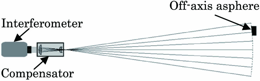
Null testing of an asphere is divided into three types according to the compensator that is used: reflective type, refractive type, and diffractive type. They are suitable for different situations. For an off-axis asphere’s optical null testing, the compensator is still an on-axis asphere, but that off-axis aphere testing uses part of the wavefront. In this context, we choose the refractive compensator to perform our measurement experiment; Fig.
![]()
Figure 1.Schematic of null compensating interferometry.
A SMR is placed on a testing target. The laser tracker receives the light reflected by the SMR and acquires the center position
The translation and rotation matrix is
The rotation matrix is
Figure
![]()
Figure 2.Diagram of the testing procedure.
The second step is to collect feature data; i.e., moving the SMR to touch the compensator’s cylinder and acquire the optical axis’s data from the cylinder’s axis, moving the SMR to touch the reference surfaces on the asphere’s block, then obtaining the geometrical center of the off-axis asphere through coordinate processes such as translation, intersection, and so on.
The third step is to build a coordinate system; i.e., using the three reference surfaces of a standard cube which aligns to the optical path to establish a coordinate system. Let the
Finally, obtaining the distance from the geometrical center point of the off-axis asphere to the optical axis, then subtracting the nominal off-axis distance, the eccentricity of the off-axis asphere is acquired.
Figure
![]()
Figure 3.Sketch of the eccentricity measurement layout.
As aforementioned, we know that measurement with a laser tracker is a contact-type method, which acquires data indirectly by touching the reference surface. Factors that impact the measuring accuracy are as follows:
We measured the eccentricity of an off-axis aspherical mirror, it has a circular aperture, and the nominal off-axis distance is 550 mm. There are five reference planes on the block: four side planes and a bottom plane, and the flatness of surfaces are excellent; all are less than 10 μm. Before measurement, using a Zeiss coordinate measuring machining (CMM), and a PRISMO navigator, we tested the distances from the geometrical center point to the three references (two side planes and the bottom plane); they are, respectively, 410.833, 410.819, and 72.040 mm. Thus, conversely, when we measure the reference surfaces with a laser tracker, we can obtain the geometrical center point coordinates by processes such as translation, intersection, and so on.
First of all, we should set the interferometer, compensator, and off-axis aspherical mirror into a right position relationship. When measuring the eccentricity of an off-axis asphere, the laser tracker should be put at a position where it can “see” every feature involved. After all are well-settled, we measure according to the aforementioned procedure; Fig.
![]()
Figure 4.Photograph of an eccentricity measurement.
After collecting all necessary information, next we should set a coordinate system as aforementioned. The coordinates system’s origin is constructed at the vertex of the off-axis asphere.
We have made five groups of measurement experiments separately; their results are as follows: 550.450, 550.413, 550.462, 550.447, and 550.433 mm. The average of these results is 550.441 mm. The uncertainty of the measurement is analyzed (Table
| Item | Error | Remark |
|---|---|---|
| Cylindricity of Compensator | ||
| Eccentricity of Compensator | ||
| Deflection of Compensator | ||
| Flatness of Asphere | ||
| Laser Tracker | Distance accuracy: | FARO (ION), interferometer), distance accuracy and angle accuracy are all typical values |
| Total | Root-sum squared (RSS) of individual errors. |
Table 1. Uncertainty Analysis
A measurement method of the eccentricity of an off-axis asphere with a high-precision, portable laser tracker is presented in this Letter. The method has the following advantages: simple principle, convenient operation, good repeatability, and high accuracy. A measurement experiment is conducted by analyzing a circular off-axis asphere; the results show that the synthetic accuracy can reach 0.1859 mm, which is 6.2% of the tolerance belt (
References
[1] B. Du, L. Li, Y. Huang. Chin. Opt. Lett., 6, 569(2008).
[2] R. N. Wilson. Reflecting Telescope Optics II, 169(2001).
[3] J. Chang, M. Zou, R. Wang, S. Feng, M. M. Talha. Chin. Opt. Lett., 8, 1082(2010).
[4] D. M. Gale. Proc. SPIE, 7018, 70183M(2008).
[5] R. Li. Opt. Precis. Eng., 3, 477(2012).
[6] X. Wang, L. Zheng. Acta Opt. Sin., 31, 0812010(2011).
[7] D. Malacara. Optical Shop Testing, 743(1992).

Set citation alerts for the article
Please enter your email address
© Copyright 2018-2021 | Chinese Laser Press. All Rights Reserved 沪ICP备15018463号-20