• Chinese Optics Letters
  • Vol. 21, Issue 3, 033601 (2023)
Yingke Ji1, Xin Xie1、*, Liang Fang1、**, Yisong Zhu2, Jianlin Zhao1, and Xuetao Gan1
Author Affiliations
  • 1Key Laboratory of Light-Field Manipulation and Information Acquisition, Ministry of Industry and Information Technology, and Shaanxi Key Laboratory of Optical Information Technology, School of Science and Technology, Northwestern Polytechnical University, Xi’an 710129, China
  • 2Institute of Fundamental and Frontier Sciences, University of Electronic Science and Technology of China, Chengdu 610054, China
  • show less
    DOI: 10.3788/COL202321.033601 Cite this Article Set citation alerts
    Yingke Ji, Xin Xie, Liang Fang, Yisong Zhu, Jianlin Zhao, Xuetao Gan. Cylindrical vector beam generator on photonic crystal cavity integrated with metal split ring nanoresonators[J]. Chinese Optics Letters, 2023, 21(3): 033601 Copy Citation Text show less
    (a) Schematic of the silicon PPC cavity with six cutting air holes for generating the CV beam. (b) Intensity distribution of the cavity mode. The upper right inset depicts the polarization directions of the field, and the bottom right hexagon depicts the Brillouin zone of the PPC slab. (c) Far-field intensity distribution of the generated CV beam; the white arrows denote the polarization directions. (d), (e) Phase diagrams of right-handed and left-handed circular polarization components of the CV beam.
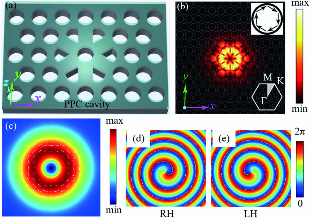
    Fig. 1. (a) Schematic of the silicon PPC cavity with six cutting air holes for generating the CV beam. (b) Intensity distribution of the cavity mode. The upper right inset depicts the polarization directions of the field, and the bottom right hexagon depicts the Brillouin zone of the PPC slab. (c) Far-field intensity distribution of the generated CV beam; the white arrows denote the polarization directions. (d), (e) Phase diagrams of right-handed and left-handed circular polarization components of the CV beam.
    (a) Schematic of the hybrid cavity with an Au SRR covered on a D-type PPC cavity. The silicon PPC slab (refractive index n = 3.37) has a thickness of t = 220 nm and lattice constant of a = 370 nm, the diameter of the air-holes is D = 0.34a, and the cutting air holes have a width of D′ = 0.8D. Geometrical parameters of the SRR: arm length L1 = 130 nm and L2 = 140 nm; arm width w = 27.5 nm; thickness d = 35 nm; gap distance between two arms gx = 75 nm; gap depth gy = 90 nm. The black dash denotes the cutting direction of the PPC cavity. (b) Surface charge distribution of the SRR as it couples with the PPC cavity. The bottom is the calculated near field of the PPC cavity (at z = 100 nm above the PPC slab), where gray arrows indicate the polarization directions. (c)–(g) Far-field intensity distributions of the hybrid SRR-PPC cavity (at z = 5 µm above the SRR) with the SRR opening along different directions, where white arrows represent the polarization directions. The upper right inset depicts the schematic of the SRR with different orientation angles, respectively.
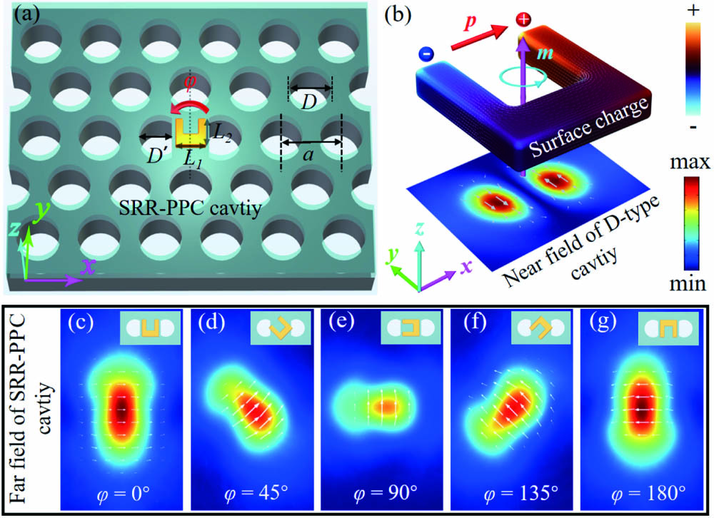
    Fig. 2. (a) Schematic of the hybrid cavity with an Au SRR covered on a D-type PPC cavity. The silicon PPC slab (refractive index n = 3.37) has a thickness of t = 220 nm and lattice constant of a = 370 nm, the diameter of the air-holes is D = 0.34a, and the cutting air holes have a width of D = 0.8D. Geometrical parameters of the SRR: arm length L1 = 130 nm and L2 = 140 nm; arm width w = 27.5 nm; thickness d = 35 nm; gap distance between two arms gx = 75 nm; gap depth gy = 90 nm. The black dash denotes the cutting direction of the PPC cavity. (b) Surface charge distribution of the SRR as it couples with the PPC cavity. The bottom is the calculated near field of the PPC cavity (at z = 100 nm above the PPC slab), where gray arrows indicate the polarization directions. (c)–(g) Far-field intensity distributions of the hybrid SRR-PPC cavity (at z = 5 µm above the SRR) with the SRR opening along different directions, where white arrows represent the polarization directions. The upper right inset depicts the schematic of the SRR with different orientation angles, respectively.
    Calculated coupling efficiency and far-field scattering intensity as a function of the orientation angle φ.
    Fig. 3. Calculated coupling efficiency and far-field scattering intensity as a function of the orientation angle φ.
    (a) Schematic of the SRR-PPC hybrid cavity for generating CV beams with tailorable polarization; (b) calculated emission spectra of CV mode from the SRR-PPC cavity with the orientation angle φ varying from 0° to 90°; the dashed line denotes the resonance wavelength of the CV mode in the PPC cavity without SRR, whose emission spectrum is shown in the inset. (c)–(f) Calculated far-field intensity distributions (at z = 5 µm above the SRR) of the CV beams. The arrows denote the polarization directions.
    Fig. 4. (a) Schematic of the SRR-PPC hybrid cavity for generating CV beams with tailorable polarization; (b) calculated emission spectra of CV mode from the SRR-PPC cavity with the orientation angle φ varying from 0° to 90°; the dashed line denotes the resonance wavelength of the CV mode in the PPC cavity without SRR, whose emission spectrum is shown in the inset. (c)–(f) Calculated far-field intensity distributions (at z = 5 µm above the SRR) of the CV beams. The arrows denote the polarization directions.
    (a)–(c) Far-field angular distributions of the SRR-PPC cavity mode for φ = 0°, 90°, and 180°, respectively; (d) calculated collection efficiency as a function of φ; blue dashed line marks the value of collection efficiency of the PPC cavity without SRRs; inset shows the far-field angular distribution of the CV mode in the PPC cavity without SRRs.
    Fig. 5. (a)–(c) Far-field angular distributions of the SRR-PPC cavity mode for φ = 0°, 90°, and 180°, respectively; (d) calculated collection efficiency as a function of φ; blue dashed line marks the value of collection efficiency of the PPC cavity without SRRs; inset shows the far-field angular distribution of the CV mode in the PPC cavity without SRRs.
    φQVm(λ/nslab)3Q/Vm
    PPC without SRRs10890.7211512.5
    860.0471829.8
    30°140.90.0612309.8
    60°199.20.0613265.6
    90°2350.0554272.7
    Table 1. Calculated Q Factor, Mode Volume Vm, and Q/Vm before and after the Integration of SRRs
    Yingke Ji, Xin Xie, Liang Fang, Yisong Zhu, Jianlin Zhao, Xuetao Gan. Cylindrical vector beam generator on photonic crystal cavity integrated with metal split ring nanoresonators[J]. Chinese Optics Letters, 2023, 21(3): 033601
    Download Citation