Abstract
We propose to use the low-coherence property of amplified spontaneous emission (ASE) noise to mitigate optical crosstalk, such as spatial, polarization, and modal crosstalk, which currently limits the density of photonic integration and fibers for dense space-division multiplexing. High optical crosstalk tolerance can be achieved by ASE-based low-coherence matched detection, which avoids dedicated optical lasers and uses spectrally filtered ASE noise as the signal carrier and as a matched local oscillator. We experimentally demonstrate spatial and modal crosstalk reduction in multimode fiber (MMF) and realize mode- and wavelength-multiplexed transmission over 1.5-km MMF supporting three spatial modes using a single ASE source. Performance degradation due to model dispersion over MMF is experimentally investigated.1. INTRODUCTION
In order to enable continuous fiber capacity enhancement, lower cost, and energy consumption per bit, space-division multiplexing (SDM), using multiple spatial channels supported by multimode fiber (MMF) and multicore fiber (MCF) [1], and dense photonic integration have come into the spotlight. However, increasing the spatial density in integrated devices and fiber components enhances the crosstalk (XT) issues, as illustrated in Fig. 1. For example, optical XT induced by waveguide sidewall scattering and sidewall roughness constrains the spatial density of photonic integration [2]. A limited number of fiber cores can be integrated into a single MCF with a mechanically reliable cladding size due to the large core-to-core pitch required for low XT. The suppression of XT between neighboring cores becomes an issue if the number of cores increases in a limited cladding size [3].
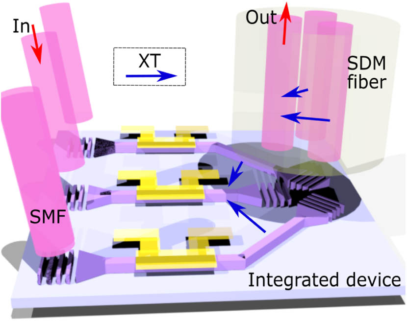
Figure 1.Illustration of optical crosstalk from space-division multiplexing (SDM) and photonic integration.
Mode-division multiplexing (MDM) using multiple spatial modes provided by MMF has obtained great achievements in recent years. A current demonstration utilizes a full set of 45 spatial modes of a conventional 50-μm MMF [4]. In the stage of digital signal processing (DSP), to recover scrambled signals due to mode coupling over MMF transmission, multiple-input–multiple-output (MIMO)-based DSP is commonly applied [5]. Employing space multiplexers (SMUXs) with mode-group selectivity [6] better than and MMF with negligible coupling between mode groups, each mode group can be recovered separately, and the dimension of MIMO can be downsized to reduce computational complexity. The photonic lantern has become one of the most successful space multiplexing schemes, which allows low-loss transformation of an array of single modes to spatial modes guided by the MMF [7]. However, in order to use all spatial and polarization modes, MIMO-based DSP is still indispensible due to strong degenerate mode coupling. Therefore, cost-efficient solutions to mitigate the optical XT between the waveguides, cores, or modes cannot only enhance space utilization efficiency, but also enable the implementation of integrated devices and SDM fibers into cost-sensitive applications such as access network and data center networks without introducing additional computation complexity.
In this paper, we discuss our recent work on optical XT mitigation employing the short coherence length property of amplified spontaneous emission (ASE) noise [8]. It employs a low-cost ASE source as both the signal carrier and a local oscillator (LO), and matched detection is applied at the receiver. The low coherence property of broadband light sources has been widely applied in optical measurements such as optical coherence tomography (OCT) [9] and refractive index characterization [10], and in optical steganography for secure optical communication [11]. We extend our study and realize a cost-efficient wavelength division multiplexing (WDM) low-coherence transmitter scheme using a single ASE source [12]. Wavelength- and mode-multiplexed transmission with XT mitigation over 1.5-km MMF supporting three spatial modes is demonstrated. Waveform distortion due to high-order model dispersion is experimentally investigated.
Sign up for Photonics Research TOC. Get the latest issue of Photonics Research delivered right to you!Sign up now
2. PRINCIPLE OF CROSSTALK MITIGATION USING ASE SOURCE
Figures 2(a) and 2(b) illustrate XT generation in standard coherent detection and optical XT mitigation employing ASE noise and matched detection. A single frequency laser is used as the LO and the signal carrier in standard coherent detection. Due to the long coherence length of continuous-wave (CW) light, both signal and XT will have strong interference with the LO at the coherent receiver. Therefore, any XT from the transmitted signal within the detection bandwidth cannot be distinguished [Fig. 2(a)].

Figure 2.Schematic of (a) crosstalk induced by coherent detection and (b) crosstalk mitigation using low-coherence matched detection. (, modulated ASE bandwidth; , signal bandwidth; , temporal path length difference between the signal and LO.)
As the same ASE is used as the LO and signal carrier rather than a single-frequency laser, the XT can be significantly reduced. In low-coherence matched detection, the signal is carried by ASE noise whose bandwidth () is larger than that of the signal (). After electronic frequency filtering to the baud rate, which can be hardware (naturally limited by the bandwidth of the photodetectors) or digital, the filtered signal power is much larger than the filtered XT power [Fig. 2(b)]. In the experiments, filtering is applied in the digital domain without employing any electronic components. In the low-coherence matched detection, the measured quantity can be written as where and represent the signal and XT, which are carried by the ASE sources and , respectively. Due to the low temporal coherence of ASE, and can come from the same source: where is the introduced time delay. As long as is larger than the source’s coherence length , and are not matched, and the detected bandwidth will spread over a much broader bandwidth.
ASE-based low-coherence matched detection has an analogy to spread-spectrum techniques, such as code-division multiple access (CDMA), but uses ASE’s inherent randomness to realize coding, which avoids complicated time [13] or frequency [14] schemes proposed for optical CDMA. Broadband ASE can be easily produced in any gain medium that is pumped, such as an erbium-doped fiber (EDF) or semiconductor optical amplifier (SOA), which is much simpler than most laser sources requiring dedicated cavity designs and temperature control.
3. ASE-BASED LOW-COHERENCE MATCHED DETECTION
Figure 3(a) shows the measured optical spectra of an ASE-based low-coherence source (LCS) with different bandwidth controlled by a bandwidth-tunable optical filter. The setup for measuring the coherent interference of the LCS is provided in Fig. 3(b). A polarizer is used to filter out one polarization state. Temporal coherence is characterized by employing a Mach–Zehnder interferometer. The coherence length of the ASE noise can be measured by scanning a tunable fiber delay line and using a power-meter at the receiver to detect the output power. If the optical path difference is longer than the coherence length, the coherence interference will be suppressed, which leads to a constant averaged power at the detector. Within the coherence length, power fluctuation caused by constructive and destructive interference can be measured by scanning the delay line at a constant speed.
Figure 3.(a) Measured optical spectra of an ASE-based low-coherence source (LCS) with different . (b) Setup for measuring inteferogram of a low-coherence source and (c) interferogram for an LCS with of 0.5 nm, 1 nm, and 2 nm.
Figure 3(c) shows the measured optical interferogram for ASE versus with different of 0.5 nm, 1 nm, and 2 nm, respectively. The strongest interference happens at , where the path length between two interference arms is closely matched and produces an interference peak. A 1-nm wide ASE source has a coherence length with 20-dB power drop around 5 ps (1-mm fiber), and the coherence length decreases inversely proportional to the LCS bandwidth. A small path length difference, e.g., 50 ps (10-mm fiber), can efficiently unmatch the signal and the XT channel. For a laser with a Lorentzian-shaped spectrum, the coherence length can be calculated as where is the optical bandwidth (full width at half-maximum linewidth), and is the speed of light. For a laser with 1-MHz , its is around 100 m.
The setup of ASE-based low-coherence matched detection is illustrated in Fig. 4(a). Compared to standard coherent detection, single-frequency lasers are replaced by the LCS for both signal carrier and LO, and the propagation distances for the signal and the LO to the receiver need to be equal. The LCS is first amplified and then split into two paths. One is used for generating polarization-diversity 14-Gbits/s quadrature phase-shift keyed (QPSK) signals through a dual-polarization in-phase and quadrature Mach–Zehnder modulator (DP-IQ MZM), which is driven by a two-channel digital-to-analog converter operated at 60 Gsymbols/s. The other split light is used as the LO. An electrically controlled optical tunable delay line is added in the LO path to control the time delay between the signal and LO. A standard dual-polarization coherent receiver (DP-CRx) is applied at the receiver, and signals are captured by a real-time digital oscilloscope operating at 40 Gsamples/s sampling rate with a bandwidth of 20 GHz. The polarization state of the LO is adjusted manually by a polarization controller to match that of the coherent receiver. Polarization tracking would be necessary in a real system. The modulated signal is recovered using a general MIMO-based DSP, where frequency offset compensation can be avoided due to matched detection. Figure 4(b) gives the measured bit error rate (BER) as a function of . It can be seen that within the coherence range, where the strong coherent interference occurs, signals can be recovered with low BER, and low-coherence matched detection behaves similarly to conventional coherence detection.
Figure 4.(a) Setup of ASE-based low-coherence matched detection and (b) achieved BER for ASE with different as a function of .
4. SPATIAL CROSSTALK MITIGATION
The setup for characterizing transmission performance with various spatial XT levels using low-coherence matched detection is shown in Fig. 5(a). After modulation, light is split into two using an 80/20 optical beam splitter. The 80% arm is used to emulate spatial XT, and an optical attenuator (Att) is applied in the arm to generate different XT levels. 1-m single-mode fiber (SMF) is used to create a delayed signal copy as the uncorrelated XT. Polarization-diversity 14-Gbits/s QPSK signals are sent into the receiver after combining with the XT (delayed copy). The same MIMO-based DSP is applied for signal recovery. Figure 5(b) shows the measured BER versus spatial XT for various . Even when the XT is stronger than the signal (as ), BER below can still be achieved. Further reduction in XT can be achieved by expanding , which spreads the XT power over a broader electrical bandwidth after low-coherence matched detection, as illustrated in Fig. 5. Due to the larger ratio requirement, conventional coherence detection has a higher spectrum efficiency compared to low-coherence matched detection. However, the latter is more advantageous in supporting SDM due to its high XT tolerance. And space dimension could be more efficient than frequency dimension for further scaling optical communication and achieving dense photonic integration [15]. Negligible system performance variation is observed by varying the delay fiber length as long as that is longer than the coherence length of the LCS.
Figure 5.(a) Setup for characterizing system performance with various crosstalk levels using low-coherence matched detection and (b) measured BER versus crosstalk for various .
5. POLARIZATION CROSSTALK MITIGATION
In polarization diversity, the two polarizations become fully mixed after SMF transmission, which usually necessitates MIMO-based DSP for data recovery. Figure 6(a) shows the setup for individually detecting each polarization using ASE-based low-coherence matched detection, where the XT from the other polarization is mitigated. Figure 6(b) provides the schematic of the used integrated DP-IQ MZM, which generates polarization-diversity 14-Gbits/s QPSK signals. The two polarization signals are unmatched due to a built-in 2-ps delay between - and -pol inside the modulator. We use this delay decorrelation to demonstrate polarization XT mitigation. Due to the small time difference between the two polarizations, provided by the modulator, the LCS with is applied to shorten the coherence length. Here, we do not apply MIMO processing to the two polarization signals after the DP-CRx, and each polarization is recovered separately by employing simplified DSP, which includes only the constant modulus algorithm (CMA), phase recovery, and BER calculation. Figures 6(c) and 6(e) plot the calculated BERs for both receivers of the DP-CRx versus the time delay through tuning the tunable delay line after 10-m and 5-km SMF transmission, respectively. It can be observed that both - and -pol signals can be individually recovered through matched detection with a time spacing around 2 ps. The BER varies depending on the polarization coupling matrix after transmission. After 10-m transmission, the coupling matrix is more diagonal: most -pol is detected by , and most -pol is coupled to . It makes -pol signals experience less XT from the -pol at and contributes to the better performance of -pol signals received at at a time around 4 ps compared to that at . Both polarizations are more uniformly distributed after 5-km transmission, which results in similar transmission performance at both receivers [Fig. 6(e)]. Recovered QPSK constellations of the -pol from both receivers at a time of 4 ps are present in Figs. 6(d) and 6(f) after 10-m and 5-km transmission, respectively.
Figure 6.(a) Setup for mitigating the polarization crosstalk after SMF transmission with different transmission distances; (b) schematic of the integrated DP-IQ MZM with 2-ps temporal delay between two polarization states; BER using MIMO-less DSP versus the time delay through tuning the delay line for (c) 10-m and (e) 5-km transmission; recovered QPSK constellations of the y-pol from both receivers at time around 4 ps for (d) 10-m and (f) 5-km transmission, including the results using maximum ratio combining (MRC).
Transmission performance can be further enhanced by employing diversity combining schemes [16]. Since two polarization states are coupled randomly, a maximum-ratio combining (MRC) scheme is chosen, where the same polarization signals from two receivers are weighted with respect to their calculated signal-to-noise ratios (SNRs) and summed together before DSP. QPSK constellations of the -pol using the MRC scheme are shown in Figs. 6(d) and 6(f) for 10-m and 5-km transmission, respectively. Another option to combine the information from both receivers is by employing a MIMO. Performance degradation after 5-km transmission may be contributed to the chromatic dispersion (CD) difference between the two 5-km SMFs, which slightly distorts the waveforms and unmatches the signal and LO.
6. SPATIAL AND POLARIZATION MODE CROSSTALK MITIGATION
Matched ASE sent from the transmitter is required as the LO in the ASE-based low-coherence matched detection, unlike optical CDMA, where the decoder can be separate from the transmitter. In the previous demonstrations, the signal and the matched LO were delivered through two separate optical fibers. It is more efficient to deliver many ASE-carried signals and one unmodulated ASE using a single SDM fiber, which provides multiple cores or spatial modes. Identical fiber and environmental variations are experienced by the signals and the unmodulated ASE, which makes the SDM fibers advantageous in maintaining the correlation between two, compared to using separate fibers [17]. Note that the tunable delay lines applied in the experiments are only for system characterization purposes and can be replaced by optical fibers with different lengths for decorrelation in real applications. A temperature controller can be applied at the transmitter and receiver to stabilize the phase of the optical fibers and maintain the delay if necessary. The state of polarization of the LO needs to be aligned with the input axis of the coherent receiver in both conventional coherent detection and low-coherence matched detection. A simple polarization tracking module may be needed in practice [18]. Since all the spatial signals use the same ASE source after temporal decorrelations, only one polarization-tracking module is needed at the receiver for the unmodulated ASE carrier. After polarization adjustment, the unmodulated ASE carrier can be split, individually tuned in time, and used as the matched LO for the signals transmitted over other spatial channels.
Three-mode MMF supports three spatial modes, which are , , and modes. Each LP mode has two polarizations, e.g., and [19]. Therefore, there are six spatial and polarization modes supported by the three-mode fiber. and modes are weakly coupled due to the large propagation constant difference. But the four spatial and polarization modes are degenerate and strongly coupled and require MIMO for data recovery in standard coherent detection. Figure 7(a) illustrates the spatial mode coupling over the three-mode MMF and shows the measured mode profiles before and after transmission. Figure 7(a) shows the multimode experiment where we transmit the LO on the mode and four 14-Gbits/s QPSK signals on the mode group. Photonic lanterns with mode selectivity between the and groups are used as SMUXs [6]. 1-m SMF is added before the SMUX at the transmitter to decorrelate the and modes. The 2-ps delay from the DP-IQ MZM is utilized to further unmatch the two polarizations: and modes.
Figure 7.(a) Setup for individual spatial and polarization mode detection by mitigating the modal crosstalk, (b) BER for the spatial mode: mode using only MIMO DSP, and (c) BER for the spatial and polarization mode: mode using MIMO-less DSP versus the time difference between the signal and matched LO.
We process the data in two separate ways: MIMO to receive the two polarization modes of the spatial mode and an MIMO-less reception of the . Figure 7(b) shows the BER for the mode using (instead of ) MIMO DSP as a function of the time delay between the mode and the mode, used as the LO. The broadening of the BER curve after 300-m MMF is due to the modal dispersion between the modes, which will be further discussed in the next section. Figure 7(c) shows the BER for the mode using MIMO-less DSP for 10-m MMF transmission. Due to modal dispersion, the time spread of the and modes is longer than 2 ps, which makes the time delay induced by the DP-IQ MZM not large enough to separate the two modes. Longer polarization delay could sufficiently decorrelate the two polarizations and support longer transmission reach.
7. MODAL DISPERSION IMPACT
Modal dispersion that induces wavelength-dependent mode coupling may distort the waveforms and consequently reduce the coherence between the signal and the ASE LO, especially for high-order modes [20]. In this section, we investigate the impact of modal dispersion on system performance in matched detection. The experiment setup is similar to the one shown in Fig. 7(a). To investigate the XT mitigation performance between the two spatial modes, and modes after transmission, single-polarization 12-Gbits/s QPSK signals are generated and coupled to the two modes, decorrelated using the 1-m SMF. At the receiver side, an optical switch is added to detect either the or mode with a 1-m length-matching fiber added to the mode path.
Figure 8(a) shows the measured BER as a function of when transmitting both and modes over the three-mode MMF with different distances. System performance starts to improve as increases because of the higher ratio between and , which reduces the in-band XT after matched detection. As is further enlarged, waveform distortion due to modal dispersion increases. The impact of modal dispersion becomes dominated as is larger than 6 nm, which causes system performance degradation. Modal dispersion accumulates with transmission distance, which explains the degraded performance after 1.5-km MMF transmission. A larger ASE carrier bandwidth has better XT tolerance but suffers more distortion due to modal dispersion. Therefore, a proper ASE carrier bandwidth needs to be chosen leveraging all the aspects such as transmission distance, modal dispersion, and XT level. It should be noticed that for many potential application scenarios such as denser photonic integration and on-chip SDM, the impact from modal dispersion is much less due to a small footprint [21–23]. MCF integrating multiple single-mode cores into one cladding has negligible modal dispersion and can be applied for long-distance transmission, where signal channels and the ASE carrier can be transmitted over different cores [17].
Figure 8.Measured BER with spatial mode crosstalk mitigation as a function of while transmitting both and modes over (a) 10-m, (b) 0.5-km, (c) 1-km, and (d) 1.5-km three-mode MMF.
8. WAVELENGTH- AND MODE-DIVISION MULTIPLEXED TRANSMISSION
Due to the broadness of the ASE noise, a wavlength-multiplexed ASE source can be easily built using optical filters and combiners. The setup for wavelength- and mode-multiplexed transmission over 1.5-km MMF with modal XT mitigation using ASE-based matched detection is shown in Fig. 9(a). Four wavelength channels with , centered at 1543.9 nm, 1547.1 nm, 1550.3 nm, and 1553.5 nm, were created by employing a wavelength-selective switch (WSS), and their channel spacing was set to 400 GHz. Current channel spacing is limited mainly by the sharpness of the optical filters applied at the receiver. We transmitted the LO on the mode and two decorrelated 12-Gbits/s signals over the and modes. We used two optical bandpass filters for demultiplexing the WDM channels. Optical spectra for each spatial mode after 10-m and 1.5-km MMF transmission are shown in Figs. 9(b) and 9(c), respectively. Negligible optical spectrum power fluctuation can be observed for the mode for the two transmission distances. However, both modes present fast and strong optical spectrum variation, especially after 1.5-km MMF transmission. It indicates the high-order modes such as modes experienced larger modal dispersion than the mode [20], which becomes the main limitation for the current setup.
Figure 9.(a) Setup for wavelength- and mode-multiplexed transmission over 1.5-km MMF with modal crosstalk mitigation using ASE-based matched detection; optical spectra of the wavelength-multiplexed signal after (b) 10-m and (c) 1.5-km 3-mode MMF transmission; recovered QPSK constellations and measured BER for (d) the mode using a CW laser with a 100-kHz linewidth, and (e) both and modes with at four wavelengths.
In order to verify the XT mitigation capability of low-coherence matched detection, system performance is compared using either the ASE source with or a CW laser with a linewidth of 100 kHz at the same center wavelength. Figure 9(d) gives the recovered QPSK constellations and measured BER for the mode as the CW laser is applied. Due to the strong modal XT within the mode group, signal cannot be recovered properly using only the MIMO. In comparison, employing the ASE source with , BERs for both modes at all four wavelengths are below in Fig. 9(e), which indicates the strong XT tolerance of low-coherence matched detection.
9. CONCLUSION
In conclusion, we experimentally demonstrated spatial, polarization and modal XT mitigation by employing a simple ASE source for both signal and LO in coherent matched detection. SDM fiber can be used to deliver both signal and matched LO through different cores or modes to the receiver. Compared to traditional coherent detection, there are three main advantages of employing low-coherence matched detection. First, it replaces an array of single-frequency lasers with a single low-coherence ASE noise source to support SDM and WDM. Low-cost broadband ASE can be easily produced and avoid dedicated laser cavity designs and sophisticated operating control circuits, which are inevitable for single-frequency lasers. Second, it allows the usage of optical components and fiber with large optical XT, which can significantly ease the fabrication and assembly requirements and lower the component and system cost. Low-coherence matched detection is a universal solution and not limited to the demonstrated mode-division multiplexed transmission over MMF. It will be beneficial for dense fiber- and component-level integration and can support short- and long-distance transmission in potentially using the SDM fiber such as MMF or MCF. Third, its low coherence property can be used for physical-layer optical encryption for secure optical transmission [11], which cannot be accomplished by employing conventional coherent detection.
References
[1] D. J. Richardson, J. M. Fini, L. E. Nelson. Space-division multiplexing in optical fibres. Nat. Photonics, 7, 354-362(2013).
[2] D. Melati, F. Morichetti, G. G. Gentili, A. Melloni. Optical radiative crosstalk in integrated photonic waveguides. Opt. Lett., 39, 3982-3985(2014).
[3] K. Saitoh, S. Matsuo. Multicore fiber technology. J. Lightwave Technol., 34, 55-66(2016).
[4] R. Ryf, N. K. Fontaine, S. Wittek, K. Choutagunta, M. Mazur, H. Chen, J. C. Alvarado-Zacarias, R. Amezcua-Correa, M. Capuzzo, R. Kopf, A. Tate, H. Safar, C. Bolle, D. T. Neilson, E. Burrows, K. Kim, M. Bigot-Astruc, F. Achten, P. Sillard, A. Amezcua-Correa, J. M. Kahn, J. Schröder, J. Carpenter. High-spectral-efficiency mode-multiplexed transmission over graded-index multimode fiber. European Conference on Optical Communication (ECOC), 1-3(2018).
[5] R. G. H. van Uden, C. M. Okonkwo, H. Chen, H. de Waardt, A. M. J. Koonen. Time domain multiplexed spatial division multiplexing receiver. Opt. Express, 22, 12668-12677(2014).
[6] B. Huang, N. K. Fontaine, B. G. Roland Ryf, S. G. Leon-Saval, R. Shubochkin, R. L. Y. Sun, G. Li. All-fiber mode-group-selective photonic lantern using graded-index multimode fibers. Opt. Express, 23, 224-234(2015).
[7] T. A. Birks, I. Gris-Sánchez, S. Yerolatsitis, S. G. Leon-Saval, R. R. Thomson. The photonic lantern. Adv. Opt. Photon., 7, 107-167(2015).
[8] H. Chen, N. K. Fontaine, R. Ryf, J. C. Alvarado, J. van Weerdenburg, R. Amezcua-Correa, C. Okonkwo, T. Koonen. Optical crosstalk reduction using amplified spontaneous emission. Optical Fiber Communications Conference and Exposition (OFC), M4G.5(2018).
[9] T. Mitsui. Dynamic range of optical reflectometry with spectral interferometry. Jpn. J. Appl. Phys., 38, 6133-6137(1999).
[10] H. Maruyama, S. Inoue, T. Mitsuyama, M. Ohmi, M. Haruna. Low-coherence interferometer system for the simultaneous measurement of refractive index and thickness. Appl. Opt., 41, 1315-1322(2002).
[11] B. Wu, Z. Wang, Y. Tian, M. P. Fok, B. J. Shastri, D. R. Kanoff, P. R. Prucnal. Optical steganography based on amplified spontaneous emission noise. Opt. Express, 21, 2065-2071(2013).
[12] Y. Huang, H. Chen, H. Huang, Y. Song, Z. Li, N. K. Fontaine, R. Ryf, J. C. Alvarado, R. Amezcua-Correa, M. Wang. Mode-multiplexed transmission with crosstalk mitigation using amplified spontaneous emission (ASE). Conference on Lasers and Electro-Optics (CLEO), SM1G.2(2019).
[13] M. Marhic. Coherent optical CDMA networks. J. Lightwave Technol., 11, 854-864(1993).
[14] T. Hamanaka, X. Wang, N. Wada, A. Nishiki, K. Kitayama. Ten-user truly asynchronous gigabit OCDMA transmission experiment with a 511-chip SSFBG en/decoder. J. Lightwave Technol., 24, 95-102(2006).
[15] P. J. Winzer. Making spatial multiplexing a reality. Nat. Photonics, 8, 345-348(2014).
[16] D. G. Brennan. Linear diversity combining techniques. Proc. IRE, 47, 1075-1102(1959).
[17] B. J. Puttnam, J. Sakaguchi, J. M. D. Mendinueta, W. Klaus, Y. Awaji, N. Wada, A. Kanno, T. Kawanishi. Investigating self-homodyne coherent detection in a 19 channel space-division-multiplexed transmission link. Opt. Express, 21, 1561-1566(2013).
[18] Z. Wang, C. Xie. Automatic optical polarization demultiplexing for polarization division multiplexed signals. Opt. Express, 17, 3183-3189(2009).
[19] L. Grüner-Nielsen, Y. Sun, J. W. Nicholson, D. Jakobsen, K. G. Jespersen, J. R. Lingle, B. Pálsdóttir. Few mode transmission fiber with low DGD, low mode coupling, and low loss. J. Lightwave Technol., 30, 3693-3698(2012).
[20] M. B. Shemirani, J. M. Kahn. Higher-order modal dispersion in graded-index multimode fiber. J. Lightwave Technol., 27, 5461-5468(2009).
[21] D. Zhou, C. Sun, Y. Lai, Y. Yu, X. Zhang. Integrated silicon multifunctional mode-division multiplexing system. Opt. Express, 27, 10798-10805(2019).
[22] S. Wang, H. Wu, H. K. Tsang, D. Dai. Monolithically integrated reconfigurable add-drop multiplexer for mode-division-multiplexing systems. Opt. Lett., 41, 5298-5301(2016).
[23] L.-W. Luo, N. Ophir, C. P. Chen, L. H. Gabrielli, C. B. Poitras, K. Bergmen, M. Lipson. WDM-compatible mode-division multiplexing on a silicon chip. Nat. Commun., 5, 3069(2014).


