
Xueling Li, Yuanqing Wang, "Autostereoscopic display with bicylindrical lens based on temporal-spatial multiplexing," Chin. Opt. Lett. 20, 033301 (2022)
- Chinese Optics Letters
- Vol. 20, Issue 3, 033301 (2022)
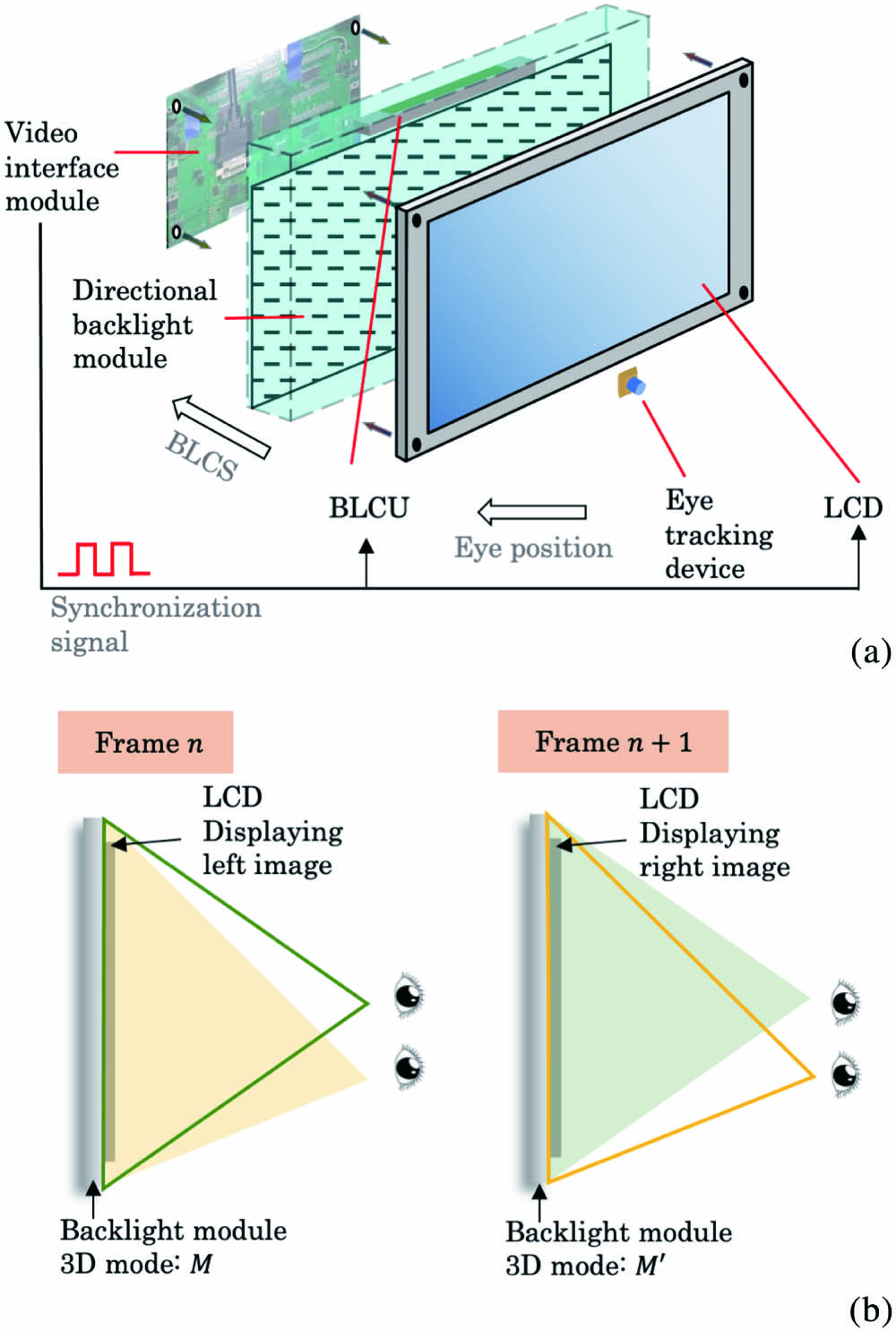
Fig. 1. (a) Overall structure and signal control of the system. (b) Temporal-spatial multiplexing technique.
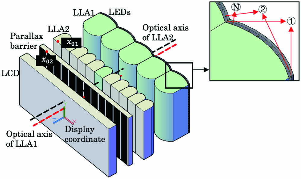
Fig. 2. Structure of the designed directional backlight module.
Fig. 3. (a) Design of LLA1. (b) The formation of view zones.
Fig. 4. Diamond-shaped area of view zone.
Fig. 5. Simulation result of LLA1.
Fig. 6. Geometric MTF of the bicylindrical lens.
Fig. 7. Structure of the prototype. (a) Outlook of the prototype. (b) Bicylindrical lens. S1 and S2 are the two curved surfaces of LLA1. (c) Overall structure.
Fig. 8. In (a) and (c), the LCD is displaying the left and right building images, respectively. In (b) and (d), the LCD is displaying the pure white image and the directional backlight projects light to the corresponding view zone at the optimal viewing distance.
Fig. 9. Crosstalk evaluation. (a) Light distribution for 10 views. (b) Crosstalk for the two middle view zones (VZ5 and VZ6). (c) Crosstalk for VZ8 and VZ9 with large viewing angle.
|
Table 1. Specifications for the LCD Panel
|
Table 2. Parameters for the Two Lens Arrays
|
Table 3. Summary of the System Performance


Set citation alerts for the article
Please enter your email address

© Copyright 2018-2021 | Chinese Laser Press. All Rights Reserved 沪ICP备15018463号-20