
Xueling Li, Yuanqing Wang, "Autostereoscopic display with bicylindrical lens based on temporal-spatial multiplexing," Chin. Opt. Lett. 20, 033301 (2022)
- Chinese Optics Letters
- Vol. 20, Issue 3, 033301 (2022)
Abstract
1. Introduction
Autostereoscopic display has a thriving prospect in many research areas[
To improve the performance of autostereoscopic display systems, a temporal-spatial multiplexing technique is introduced. It usually contains a directional backlight unit[
We propose a temporal-spatial multiplexed autostereoscopic display system in this paper. The system consists of a directional scanning backlight, a LCD panel, and an eye tracking device. To correct optical aberration, a bicylindrical lens is specially designed for the directional backlight module. In this prototype, 10 view zones are available. The minimum crosstalk is 6%, and the viewing angle is
2. System Design and Analysis
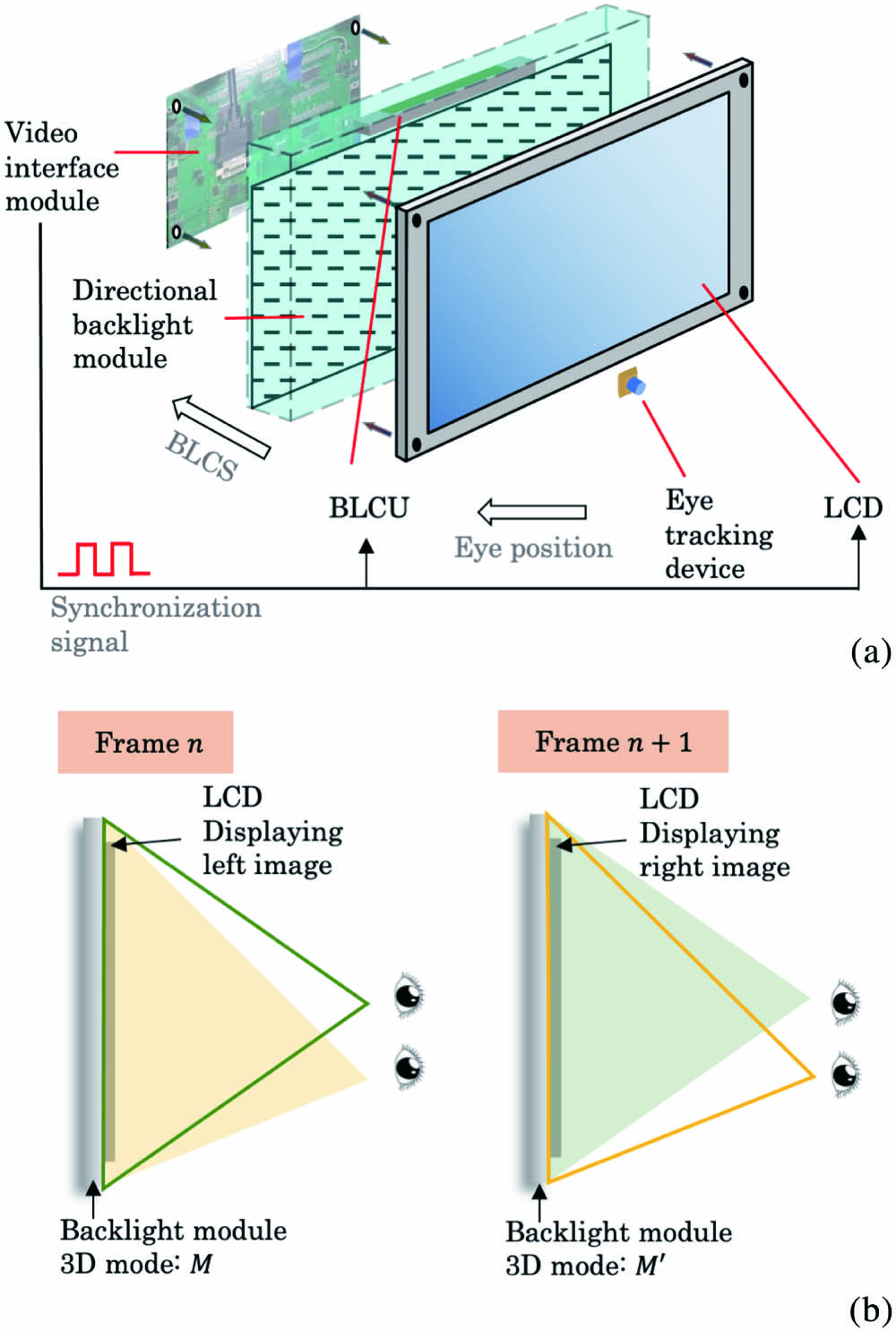
The overall configuration of the temporal-spatial multiplexed autostereoscopic display system consists of the following parts: directional backlight module, backlight control unit (BLCU), LCD panel of high refreshing rate, and eye tracking device. The eye tracking device obtains the viewers’ left and right eye positions in real time, sending them back to the BLCU, where the backlight control signal (BLCS) is generated. The directional backlight module produces display modes accordingly. This progress is shown in Fig. 1(a). Channel separation, as the core technology of autostereoscopic display, is realized through temporal-spatial multiplexing. The left and right images are displayed by the LCD with full resolution frame by frame, and they are projected by the directional backlight module alternatively to the corresponding eye position. To do that, the directional backlight has to be in synchronization with the LCD panel. This principle can be illustrated in Fig. 1(b). For example, under 3D mode, if the LCD is displaying the left image during frame
![]()
Figure 1.(a) Overall structure and signal control of the system. (b) Temporal-spatial multiplexing technique.
2.1. Optical structure
The structure of the designed directional backlight module is illustrated in Fig. 2. The main components include the backlight board, bicylindrical lens array (LLA1), lenticular lens array (LLA2), parallax barrier, and other optical films. The backlight board is placed on the focal plane of LLA1. They are divided into
![]()
Figure 2.Structure of the designed directional backlight module.
Lenses of LLA1 can refract different groups of LEDs to parallel light of different angles. The two LLAs are placed with their cylindrical surface facing each other. Different angles of parallel light converge into light strips at different positions after LLA2. The parallax barrier is set with an optical interval of
2.1.1. Design of bicylindrical lens
To form light strips with small width after LLA2, the parallelism of the incident light is important. Ideally, parallel light refracted by the cylindrical lens will form a convergence point on the focal plane. The positions of the convergence points vary on the focal plane with the angle of the incident light. However, in reality, the aberration of the lens has a great influence on the convergence of parallel light. Due to aberration, the incident parallel light with larger angle will not converge to a single point. The equivalent converging point is away from the focal plane, or, in other words, the focal plane is a curved plane rather than a flat one. So, according to optical path reversibility, in order to obtain parallel light, the curvature of the focal plane needs to be determined. As shown in Fig. 3(a), assume
![]()
Figure 3.(a) Design of LLA1. (b) The formation of view zones.
In this way, the coordinate of the light source that forms parallel light of angle
For all the symbols of parameters mentioned in the above formulas, they should be added with a minus sign according to the rules while calculating.
The coordinates of
2.1.2. Principle of the optical imaging
As shown in Fig. 3(a), for
Parallel light focused by LLA2 forms light strips on the focal plane of LLA2, as demonstrated in Fig. 3(b).
The procedure to determine view zone position
The center distance of view zones formed by adjacent LEDs is supposed to be Eq. (8):
The relationship between
2.2. Directional backlight controlled by eye tracking device
In order to project correct image information to the corresponding eye location, a high-speed real-time eye tracking device is introduced into the autostereoscopic display system.
The system is composed of a low-resolution thermal infrared (IR) camera, a high-resolution RGB camera, and an industrial computer. Since the human face is very prominent in the IR image, it is easier and faster to detect human faces with an IR camera. Then, the detected human face information can be used to guide the industrial computer to locate eye position in the RGB camera. With IR guiding, the time of detecting eye positions in RGB images can be greatly reduced. Assume the pixel coordinate of the eye position detected in the RGB image is
In Eq. (9), K is the transformation matrix from the camera coordinate to the pixel coordinate; R and T represent the rotation matrix and translation matrix from the world coordinate to the camera coordinate, respectively. They can be acquired through camera calibration. Therefore, the determined eye position in the pixel coordinate can be transformed into the display coordinate, which can then be transformed into the corresponding backlight mode according to Eq. (7).
For autostereoscopic display, the view zone is actually a diamond-shaped area, as shown in Fig. 4. Therefore, viewing distance
![]()
Figure 4.Diamond-shaped area of view zone.
Later, in Section 3, it can be verified that for our prototype the calculation error
3. Experiments and Results
A bicylindrical lenticular lens is designed according to Eq. (1). By analyzing the parallelism of the light and the geometric modulation transfer function (MTF) of the bicylindrical lens, the optimization of the aberration can be verified. As shown in Fig. 5, we compare the simulation results of the customized lenslet and normal lenslet. The parallelism can be qualitatively judged by the radiation range on the observation plane. Figures 5(a) and 5(b) are the irradiance maps of the bicylindrical lens when the LED is at different positions. Despite the light attenuation, the distribution is similar on either the near or far observation plane. Figures 5(c) and 5(d) are the irradiance maps of the cylindrical lens when the LED is at different positions. It is obvious that the light distribution range becomes larger when it propagates to greater distance, when the LED is placed on the edge of the lens. However, when the LED is placed at the center of the lens, this divergence is not notable.
![]()
Figure 5.Simulation result of LLA1.
In addition, Fig. 5(e) is the normalized irradiance distribution of the parallel light by the bicylindrical lens and cylindrical lens when the LED is placed on the edge of the lens. As shown, the irradiance distribution is more even in the case of the bicylindrical lens than in the cylindrical lens case. By calculating the standard deviation of the flat top area, where the parallel light is mainly distributed, we can intuitively distinguish which one is more uniform. The standard deviation of the bicylindrical lens
The geometric MTF of the LLA1 unit is shown in Fig. 6. As shown in Figs. 6(a) and 6(b), they are the MTF curves of the bicylindrical lens and the cylindrical lens, respectively. In each figure, there are three curves that represent different off-axis distances. It is obvious that with the increase of the distance, the MTF decreases, both in the case of the bicylindrical lens and the cylindrical lens. However, the degree of reduction is weaker in the bicylindrical lens than in the cylindrical lens. As indicated in Figs. 6(c) and 6(d), when the off-axis distance is small, the difference of MTF is smaller, yet still there is a minor improvement from the cylindrical lens to the bicylindrical lens. When the off-axis distance is large, the improvement is rather significant.
![]()
Figure 6.Geometric MTF of the bicylindrical lens.
In general, through the evaluation of the simulation result, our bicylindrical lens is indeed capable of better image quality.
A prototype based on the principle discussed above is set up, and the performance is verified through a series of experiments. Figure 7(a) shows the layout of the prototype, while Fig. 7(b) shows the structure of the designed bicylindrical lens. The LEDs are arranged on a curved surface as well, so the light efficiency of LLA1 can be improved when the LED is on the edge of LLA1. The backlight board is composed of 10 groups of LEDs, generating 10 different view zones as VZ1–VZ10. The characteristics of the LCD used in this prototype are summarized in Table 1. In the meantime, the parameters of LLA1 and LLA2 are recorded in Table 2. Polyethylene terephthalate (PET) is the optical interval between LLA1 and LLA2. The diffusion film is a special kind that only diffuses and uniforms the longitudinal brightness. In this way, the horizontal width of the light strip is strictly controlled.
| Parameter | Value |
|---|---|
| Screen diagonal | 27 in. |
| Resolution in 3D mode | |
| Response time | 5 ms (Typ. on/off) |
| Frame rate | 120 Hz |
Table 1. Specifications for the LCD Panel
| LLA1 (mm) | LLA2 (mm) | |
|---|---|---|
| Pitch | 10 | 0.18293 |
| Focal length | 32.8 | 0.6 |
| Radius of S1 | 16.4 | 0.3 |
| Radius of S2 | 25.8 | – |
Table 2. Parameters for the Two Lens Arrays
![]()
Figure 7.Structure of the prototype. (a) Outlook of the prototype. (b) Bicylindrical lens. S1 and S2 are the two curved surfaces of LLA1. (c) Overall structure.
In this prototype,
After the eye tracking device detects and calculates eye positions, it transmits a BLCS to the BLCU. For our prototype, the calculating error of the eye position as mentioned in Eq. (10) can be determined. For the distance
For example, Fig. 8 demonstrates the effect of displaying the left image and right image that are projected to two neighboring spatial locations [Figs. 8(a) and 8(b) for VZ5, Figs. 8(c) and 8(d) for VZ6] by the directional backlight alternately. As we can see in Figs. 8(a) and 8(c), at both positions, the images can be seen clearly, indicating that the crosstalk is rather small. In Figs. 8(b) and 8(d), the displayed image is pure white with the corresponding backlight on and the rest off. The white band is where the corresponding view zone locates, and the rest of the places are dark.
![]()
Figure 8.In (a) and (c), the LCD is displaying the left and right building images, respectively. In (b) and (d), the LCD is displaying the pure white image and the directional backlight projects light to the corresponding view zone at the optimal viewing distance.
Crosstalk is one of the most critical parameters for autostereoscopic display. For the proposed autostereoscopic display scheme, the crosstalk can be calculated by Eq. (14):
![]()
Figure 9.Crosstalk evaluation. (a) Light distribution for 10 views. (b) Crosstalk for the two middle view zones (VZ5 and VZ6). (c) Crosstalk for VZ8 and VZ9 with large viewing angle.
With the increase of the viewing angle to 20 deg, such as VZ8 and VZ9, the crosstalk is increased to 8.8%, which is shown in Fig. 9(c). The distribution of the viewing zone at a large angle is sharply distributed with a slightly smaller slope. These two features undermine the display effect regarding contrast and crosstalk. The crosstalk for VZ8 is mainly contributed by VZ7 and VZ9, and the crosstalk for VZ9 is mainly contributed by VZ8 and VZ10. However, this result is much better compared to the autostereoscopic display system based on a parallax barrier or lenticular lens.
With the increase of the viewing angle, the brightness gradually decreases. The brightness difference between adjacent view zones is 10%. This may not spoil the viewing experience. But, for future perfection, the local backlight control strategy can be adopted.
Here, the performance of our system is summarized in Table 3, together in comparison with other kinds of display systems. As we can see from the table, the viewing angle of our system is improved compared with that of the free-form surface backlight (FFSB) system[
| Viewing Angle | Crosstalk | Luminance/Efficiency | |
|---|---|---|---|
| Our system | 6% at the central viewing angle, 8.8% at large viewing angle | ||
| System1 with FFSB | 7.39% at the central viewing angle | ||
| System2 with parallax barrier | 10%–15% | –/20% | |
| System3 with micro-projection dynamic backlight[ | – | – | |
| System4 with lenticular sheet and liquid crystal parallax barrier[ | Average crosstalk 17.1% | – |
Table 3. Summary of the System Performance
4. Conclusion
In this paper, an autostereoscopic 3D display system based on the spatial-temporal multiplexing technique is introduced. The system consists of a directional backlight module, BLCU, LCD panel of high refreshing rate, and eye tracking device. The directional backlight module, which forms view zones at specific locations, comprises LLA1 with larger pitch and LLA2 with smaller pitch, LEDs that are divided into 10 groups, a parallax barrier, and other optical films. To correct optical aberration and form light strips with smaller width, especially for large viewing angle, LLA1 is designed to be a bicylindrical lens. The LEDs are arranged on a curved surface so that the light efficiency can be improved when it is on the edge of LLA1. Still, the light efficiency is decreased a little when the viewing angle is large, because light can be absorbed by the parallax barrier. However, to make the exit pupil distribution more even, locally controllable backlight can be adopted in our future work. Composed of a long-wavelength IR camera and a visible spectrum camera, the eye tracking device detects the eye positions with faster speed, transforms them to a corresponding backlight mode, and transmits the mode information to the BLCU. A prototype based on our optical design is set up, and relevant experiments are carried out to verify the feasibility. The minimal crosstalk is 6%, and viewing angle is increased to
References
[1] H. Fan, Y. Zhou, J. Wang, H. Liang, P. Krebs, J. Su, D. Lin, K. Li, J. Zhou. Full resolution, low crosstalk, and wide viewing angle auto-stereoscopic display with a hybrid spatial-temporal control using free-form surface backlight unit. J. Disp. Technol., 11, 620(2015).
[2] A. K. Srivastava, J. L. de Bougrenet de la Tocnaye, L. Dupont. Liquid crystal active glasses for 3D cinema. J. Disp. Technol., 6, 522(2010).
[3] M. Lambooij, W. Ijsselsteijn, M. Fortuin, I. Heynderickx. Visual discomfort and visual fatigue of stereoscopic displays: a review. J. Imaging Sci. Technol., 53, 30201(2009).
[4] S. Lee, J. Kim, S. Lee. Behavioral circuit models of stereoscopic 3-D liquid crystal displays and shutter glasses. IEEE Trans. Electron Dev., 62, 3302(2015).
[5] K. Yoon, H. Ju, H. Kwon, I. Park, S. Kim. Diffraction effects incorporated design of a parallax barrier for a high-density multi-view autostereoscopic 3D display. Opt. Express, 24, 4057(2016).
[6] G. Lv, Q. Wang, J. Wang, W. Zhao. Multi-view 3D display with high brightness based on a parallax barrier. Chin. Opt. Lett., 11, 121101(2013).
[7] G. Lv, J. Wang, W. Zhao, Q. Wang. Three-dimensional display based on dual parallax barriers with uniform resolution. Appl. Opt., 52, 6011(2013).
[8] X. Yu, X. Sang, D. Chen, P. Wang, X. Gao, T. Zhao, B. Yan, C. Yu, D. Xu, W. Dou. 3D display with uniform resolution and low crosstalk based on two parallax interleaved barriers. Chin. Opt. Lett., 12, 121001(2014).
[9] S. Lee, J. Park, J. Heo, B. Kang, D. Kang, H. Hwang, J. Lee, Y. Choi, K. Choi, D. Nam. Autostereoscopic 3D display using directional subpixel rendering. Opt. Express, 26, 20233(2018).
[10] L. Qi, Q. Wang, J. Luo, W. Zhao, C. Song. An autostereoscopic 3D projection display based on a lenticular sheet and a parallax barrier. J. Disp. Technol., 8, 397(2012).
[11] X. Ma, W. Zhao, J. Hu, G. Lv, Q. Wang. Autostereoscopic three-dimensional display with high resolution and low cross talk using a time-multiplexed method. Opt. Eng., 57, 095105(2018).
[12] Y. Takaki. Multi-view 3-D display employing a flat-panel display with slanted pixel arrangement. J. Soc. Inf. Display, 18, 476(2010).
[13] L. Qi, Q. Wang, J. Luo, A. Wang, D. Liang. Autostereoscopic 3D projection display based on two lenticular sheets. Chin. Opt. Lett., 10, 011101(2012).
[14] K. Chien, H. D. Shieh. Time-multiplexed three-dimensional displays based on directional backlights with fast-switching liquid-crystal display. Appl. Opt., 45, 3106(2006).
[15] C. Chen, Y. Yeh, H. D. Shieh. 3-D mobile display based on Moire-free dual directional backlight and driving scheme for image crosstalk reduction. J. Disp. Technol., 4, 92(2008).
[16] H. Liang, S. An, J. Wang, Y. Zhou, H. Fan, P. Krebs, J. Zhou. Optimizing time-multiplexing auto-stereoscopic displays with a genetic algorithm. J. Disp. Technol., 10, 695(2014).
[17] J. Wang, H. Liang, H. Fan, Y. Zhou, P. Krebs, J. Su, Y. Deng, J. Zhou. High-quality autostereoscopic display with spatial and sequential hybrid control. Appl. Opt., 52, 8549(2013).
[18] D. Miyazaki, Y. Hashimoto, T. Toyota, K. Okoda, T. Okuyama, T. Ohtsuki, A. Nishimura, H. Yoshida. Multi-user autostereoscopic display based on direction-controlled illumination using a slanted cylindrical lens array. Proc. SPIE, 9011, 90111G(2014).
[19] B. Xu, Q. Wu, Y. Bao, G. Chen, Y. Wang, S. Ren. Time-multiplexed stereoscopic display with a quantum dot-polymer scanning backlight. Appl. Opt., 58, 4526(2019).
[20] B. Zhao, R. Huang, G. Lv. Micro-projection dynamic backlight for multi-view 3D display. Chin. Opt. Lett., 19, 092201(2021).


Set citation alerts for the article
Please enter your email address

© Copyright 2018-2021 | Chinese Laser Press. All Rights Reserved 沪ICP备15018463号-20