• Photonics Research
  • Vol. 11, Issue 12, 2231 (2023)
Shun-Xin Li1、2, Jia-Cheng Feng1, Yang An1, and Hong Xia1、*
Author Affiliations
  • 1State Key Laboratory of Integrated Optoelectronics, College of Electronic Science and Engineering, Jilin University, Changchun 130012, China
  • 2College of Physics, Jilin University, Changchun 130012, China
  • show less
    DOI: 10.1364/PRJ.496838 Cite this Article Set citation alerts
    Shun-Xin Li, Jia-Cheng Feng, Yang An, Hong Xia. Flexible, self-powered, and polarization-sensitive photodetector based on perovskite lateral heterojunction microwire arrays[J]. Photonics Research, 2023, 11(12): 2231 Copy Citation Text show less
    (a) Schematic diagram of 3D perovskite and 2D Ruddlesden–Popper perovskite structures; (b)–(d) schematic diagram of process for preparing (PEA)2PbBr4 microwire crystals by imprinting; (e)–(g) regioselective ion exchange preparation of (PEA)2PbBr4–(PEA)2PbBr4−xIx lateral heterojunction.
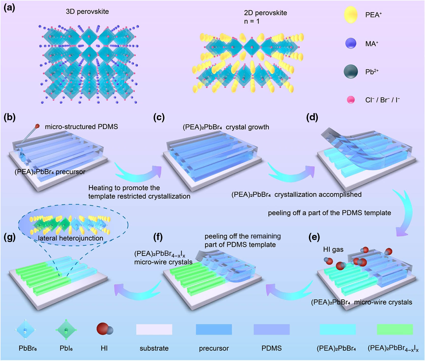
    Fig. 1. (a) Schematic diagram of 3D perovskite and 2D Ruddlesden–Popper perovskite structures; (b)–(d) schematic diagram of process for preparing (PEA)2PbBr4 microwire crystals by imprinting; (e)–(g) regioselective ion exchange preparation of (PEA)2PbBr4(PEA)2PbBr4xIx lateral heterojunction.
    (a) SEM image of the lateral heterojunction array; (b) I, Pb, Br element distribution of lateral heterojunction; (c)–(e) fluorescence microscope photos of lateral heterojunction array; (f) absorption spectrum, (g) XRD pattern, and (h) Raman spectrum of (PEA)2PbBr4−xIx, (PEA)2PbBr4, and (PEA)2PbI4; (i) typical time-resolved photoluminescence curves of (PEA)2PbBr4 and (PEA)2PbBr4−xIx.
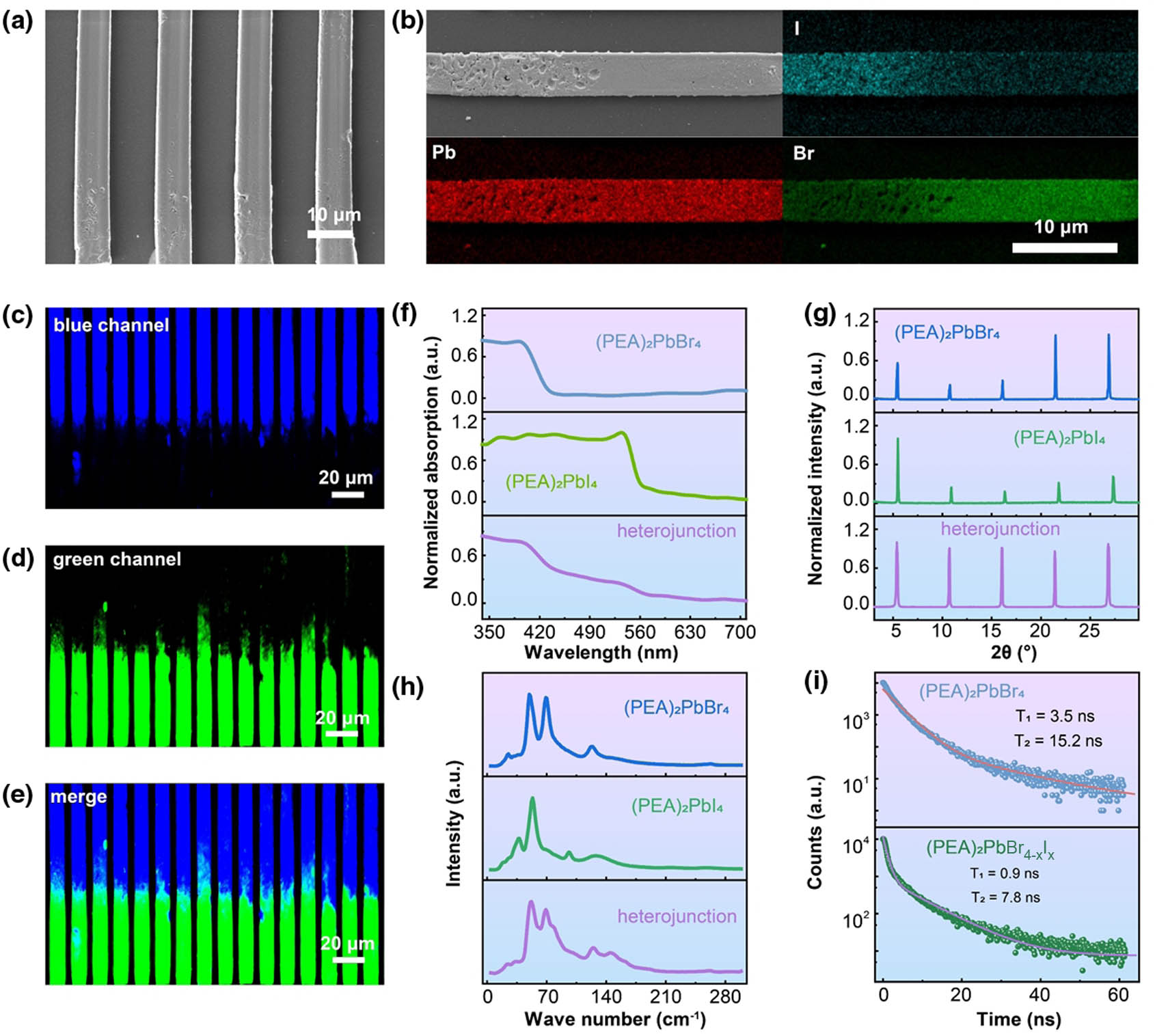
    Fig. 2. (a) SEM image of the lateral heterojunction array; (b) I, Pb, Br element distribution of lateral heterojunction; (c)–(e) fluorescence microscope photos of lateral heterojunction array; (f) absorption spectrum, (g) XRD pattern, and (h) Raman spectrum of (PEA)2PbBr4xIx, (PEA)2PbBr4, and (PEA)2PbI4; (i) typical time-resolved photoluminescence curves of (PEA)2PbBr4 and (PEA)2PbBr4xIx.
    (a) Color plot of TA spectra from (PEA)2PbBr4; (b) TA spectra at 398–410 nm; (c) TA kinetics probed at a selected wavelength of 405 nm from (a); (d) color plot of TA spectra from (PEA)2PbBr4−xIx; (e) TA spectra at 498–545 nm; (f) TA kinetics probed at a selected wavelength of 518.9 nm from (d).
    Fig. 3. (a) Color plot of TA spectra from (PEA)2PbBr4; (b) TA spectra at 398–410 nm; (c) TA kinetics probed at a selected wavelength of 405 nm from (a); (d) color plot of TA spectra from (PEA)2PbBr4xIx; (e) TA spectra at 498–545 nm; (f) TA kinetics probed at a selected wavelength of 518.9 nm from (d).
    (a) Sketch of a lateral heterojunction photodetector based on (PEA)2PbBr4−(PEA)2PbBr4−xIx; (b) I-V curve of PD under different light intensities; (c) I-t curve of the PD under different intensities of on–off light irradiation and 5 V bias; (d) variation of photocurrent and R with light intensity under 5 V bias; (e) I-t curve of PD under different on–off light intensities and 0 V bias; (f) under 0 V bias, the photocurrent and R versus light intensity.
    Fig. 4. (a) Sketch of a lateral heterojunction photodetector based on (PEA)2PbBr4(PEA)2PbBr4xIx; (b) I-V curve of PD under different light intensities; (c) I-t curve of the PD under different intensities of on–off light irradiation and 5 V bias; (d) variation of photocurrent and R with light intensity under 5 V bias; (e) I-t curve of PD under different on–off light intensities and 0 V bias; (f) under 0 V bias, the photocurrent and R versus light intensity.
    (a) Sketch of polarized light detection by the lateral heterojunction-based photodetector; (b) I-t curve of PD under light irradiation of different polarization angles; (c) photocurrent dependence on the polarization angle of the incident light. When the incident light rotates in the plane of the heterojunction: (d) photocurrent dependence on the angle of the incident light; (e) I-t curve of PD under the illumination of different incident angles. When the incident light rotates in the plane perpendicular to the heterojunction: (f) photocurrent dependence on the incident light angle; (g) I-t curve of PD under light irradiation at different incident angles.
    Fig. 5. (a) Sketch of polarized light detection by the lateral heterojunction-based photodetector; (b) I-t curve of PD under light irradiation of different polarization angles; (c) photocurrent dependence on the polarization angle of the incident light. When the incident light rotates in the plane of the heterojunction: (d) photocurrent dependence on the angle of the incident light; (e) I-t curve of PD under the illumination of different incident angles. When the incident light rotates in the plane perpendicular to the heterojunction: (f) photocurrent dependence on the incident light angle; (g) I-t curve of PD under light irradiation at different incident angles.
    (a), (b) Photocurrent change curves of PD under different bending states; (c), (d) PD performance after different bending cycles; (e), (f) PD performance after storage in air for different times.
    Fig. 6. (a), (b) Photocurrent change curves of PD under different bending states; (c), (d) PD performance after different bending cycles; (e), (f) PD performance after storage in air for different times.
    (a) SEM image of a PDMS template with a microscale striped structure. (b) AFM image of (PEA)2PbBr4 microwire crystals. (c) Fluorescence microscope photograph of (PEA)2PbBr4 microwire crystals. (d) SEM image of the cross-section of (PEA)2PbBr4 microwire crystals.
    Fig. 7. (a) SEM image of a PDMS template with a microscale striped structure. (b) AFM image of (PEA)2PbBr4 microwire crystals. (c) Fluorescence microscope photograph of (PEA)2PbBr4 microwire crystals. (d) SEM image of the cross-section of (PEA)2PbBr4 microwire crystals.
    (a) Mapping of element I after 7 days. (b) Mapping of element Br after 7 days. (c)–(e) Fluorescence microscope images of heterogeneous junctions after 7 days.
    Fig. 8. (a) Mapping of element I after 7 days. (b) Mapping of element Br after 7 days. (c)–(e) Fluorescence microscope images of heterogeneous junctions after 7 days.
    (a) Dark current of the device at a bias voltage of 5 V. (b) Variation curves of D and EQE of the device under different incident light intensities at a bias voltage of 5 V. (c) Dark current of the device at a bias voltage of 0 V. (d) Variation curves of D and EQE of the device under different incident light intensities at a bias voltage of 0 V.
    Fig. 9. (a) Dark current of the device at a bias voltage of 5 V. (b) Variation curves of D and EQE of the device under different incident light intensities at a bias voltage of 5 V. (c) Dark current of the device at a bias voltage of 0 V. (d) Variation curves of D and EQE of the device under different incident light intensities at a bias voltage of 0 V.
    Materialsλ (nm)R(A  W1)D (Jones)FlexibleLong-Term StabilityReference
    BA2PbI4BA2MAPb2I74608.12 at 30 V1.5×1012NoNA[1]
    MAPbI3xClxCsPbBr34050.39 at 1 V5.43×109NoNA[30]
    CsPbI3CsPbBr36500.125 at 0 VNA90% after 500 bending cycles85% after 15 days[2]
    MAPbI3MAPbBr3500<0.2 at 5 VNANoNA[31]
    iBA2(MA)n1PbnI3n+14050.444 at 0 V 3.463 at 1.5 V4.1×10129000 bending cyclesNA[32]
    (4-AMP)(MA)2Pb3Br10/MAPbBr34051.19×103at0  V1.26×1012NoNo obvious change after 40 days[33]
    2D/3D perovskite532<5 at 2 VNANo71% after 30 days[34]
    (4-AMP)(MA)2Pb3Br10/MAPbBr34051.5×103 at 0 V3.8×1010NoNegligible degradation after 30 days[19]
    MAPbBr3/MAPbBr3xIx532265 at 5 VNANo90% after 10 days[20]
    (PEA)2PbBr4(PEA)2PbBr4xIx365748 at 5 V 13.5 at 0 V8.2×1012at 5 V1.1×1012at 0 V78% after 3000 bending cycles81% after 144 daysThis study
    Table 1. Performance of Perovskite–Perovskite Heterojunction-Based Photodetectors
    Shun-Xin Li, Jia-Cheng Feng, Yang An, Hong Xia. Flexible, self-powered, and polarization-sensitive photodetector based on perovskite lateral heterojunction microwire arrays[J]. Photonics Research, 2023, 11(12): 2231
    Download Citation