
Bing-Yan Wei, Yuan Zhang, Haozhe Xiong, Sheng Liu, Peng Li, Dandan Wen, Jianlin Zhao. Janus vortex beams realized via liquid crystal Pancharatnam–Berry phase elements[J]. Advanced Photonics Nexus, 2022, 1(2): 026003
- Advanced Photonics Nexus
- Vol. 1, Issue 2, 026003 (2022)
Abstract
Keywords
1 Introduction
Manipulating light fields to generate spatially structured light beams1 has been attracting significant interest. In particular, vortex beams have gained a great deal of attention owing to their outstanding performances. Different from ordinary Gaussian beams, vortex beams feature helical wavefronts described by , where is the topological charge and is the angular coordinate.2,3 The spiral phase of the vortex beam, on the one hand, leads to the phase singularity at the center, resulting in the annular intensity distribution with a central dark region. On the other hand, it gives rise to the existence of the orbital angular momentum (OAM) with each photon carrying the value of (the quantum unit is the reduced Planck’s constant), which distinguishes it from the spin angular momentum (SAM) related to the circular polarization state of light. These special characteristics endow vortex beams with a broad range of applications, such as optical trapping with controlled rotation,4
Another interesting type of structured light beams that has emerged in recent years is Janus waves. First proposed by Papazoglou et al., Janus waves are a family of waves having “real” and “virtual” components located at two symmetrical foci.14 The “real” wave and the “virtual” wave are conjugate to each other under inversion of the propagation direction, just like the Roman mythological deity Janus to some extent (as shown in the upper left illustration of Fig. 3). A typical example of Janus waves is the circular Airy beam (CAB),14 which is widely known for its abruptly autofocusing property, i.e., it will keep a relatively low intensity before it abruptly autofocuses with a peak intensity increased by orders of magnitude. Owing to this distinctive property, CABs have played an important role in laser ablation,15 microparticles manipulation,16 generations of intense light bullets,17 and stimulated Raman scattering,18 and are excellent candidates for biomedicine and nanosurgery.15 Besides the well-known real focus in the forward propagation direction, identified as the Janus wave, the CAB also has a virtual focus in the inverse direction. Generally, a lens is utilized to make the “virtual” component of the Janus wave accessible.14 In addition to the aforementioned applications of the CAB, the Janus wave with two distinct foci could also be applied for phase memory preserving harmonics in strong field science.19
Taking advantage of Janus waves to drive the spiral phase is a novel way to modulate vortex beams. However, few works have been devoted to this topic so far, one of which is the study of the propagation dynamics of the proposed Janus vortex waves only theoretically.20 Therein, the spiral phases on the two focal planes have the same rotation direction, which means that the topological charge or the OAM remains unchanged, lacking a certain degree of modulation flexibility. In this work, specially designed liquid crystal (LC) Pancharatnam–Berry (PB) phase optical elements, Janus-q-plates, are proposed to experimentally realize the generation of Janus vortex beams. LCs have been widely used in display and nondisplay fields due to their outstanding electro-optical property, and the LC-mediated PB phase optical elements are remarkable candidates for multidimensional manipulation of light waves with high quality and high efficiency.21
Sign up for Advanced Photonics Nexus TOC. Get the latest issue of Advanced Photonics Nexus delivered right to you!Sign up now
2 Results and Discussion
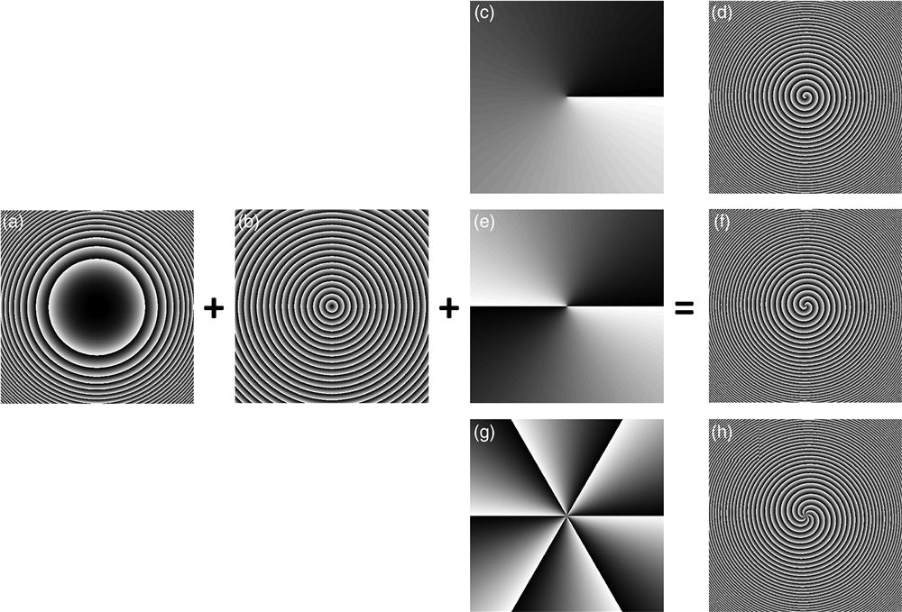
As has been mentioned above, the CAB belongs to the Janus waves family.14 The generation of CABs is commonly based on the Fourier transform (FT) patterns15,31 or the holograms calculated by the interference of a reference plane wave and the target CABs.16 Recently, a relatively easier way was proposed based on the superimposition of specific phase structures,32 realizing the efficient generation32 and modulation33 of CABs. The superimposed phase structure is derived from the asymptotic analysis of the FT of a CAB whose characteristic phase term is composed of a cubic term and a linear term. Herein, on the basis of the radial cubic phase [as shown in Fig. 1(a)] and the radial linear phase [as shown in Fig. 1(b)], we purposefully add the spiral phase [as shown in Figs. 1(c), 1(e), and 1(g)] to introduce the vortex beam component. Figure 1 shows the design principle of the newly superimposed phase structure, which can be expressed as
![]()
Figure 1.(a) Radial cubic phase; (b) radial linear phase; (c) spiral phase with
The diffraction property of the Janus-q-plate can be analyzed through Jones calculus. For the PB phase optical element under the half-wave condition with the optical axis orientation following , the Jones matrix can be expressed as34
For an incident Gaussian beam with a linear polarization state, its electric field can be expressed as
From Eq. (5), we can see that the desired PB phase modulation component consists of two parts with orthogonal SAM states: RCP component and LCP component. For the RCP component, it exhibits a helical phase front and a linear phase enhanced cubic phase modulation , revealing the generation of autofocusing CAB carrying OAM. However, for the LCP component, the phase modulation is conjugate, revealing an opposite OAM carried by the conjugate CAB. A lens can be used to bring the virtual focus of the conjugate CAB into real space14 together with the OAM and SAM. In this case, the positions of the focused beams and can be calculated via the lens equation
To implement the space-variant LC director distribution following Eq. (2), the rewritable sulfonic azo-dye SD1-based photoalignment technology and the digital micromirror device (DMD) based dynamic microlithography system are employed.35 Under linearly polarized UV light irradiation, the SD1 molecules tend to orient their absorption oscillators perpendicularly to the incident polarization direction. As the alignment layer, SD1 molecules will spread their orientation to adjacent LC molecules by intermolecular interaction. Patterned UV light with a specific polarization direction can be created through the DMD (resolution: ; pitch: ) exposure system. After an 18-step, five-time partly overlapping dynamic exposure process,36 the Janus-q-plate pattern in Fig. 1 can be precisely duplicated onto the LC cell, which is composed of two SD1-coated indium-tin-oxide glass substrates separated by spacers. After capillary filling of nematic LC E7, a director-variant PB phase element LC Janus-q-plate can thus be formed.
Figures 2(a)–2(c) exhibit the micrographs of the Janus-q-plates with , 1, and 3, respectively, which are observed under a polarized optical microscope. The greenish color of the micrographs is due to the corresponding wavelength meeting with the LC sample’s half-wave condition.37 The bright regions correspond to the LC directors at about or to one of the polarizers of the microscope, and the dark regions correspond to the angles of about 0 or . As the orientation of the LC directors gradually changes from 0 to , the bright-to-dark regions alternate twice, leading to the number of spiral fringes in the micrographs being twice that of the phase patterns shown in Figs. 1(d), 1(f), and 1(h). Therefore, times, i.e., 2, 4, and 12 times bright-to-dark alternations are observed in Figs. 2(a)–2(c), respectively. As a comparison, it can be found that with the increase of , the spiral distortion at the central part of the phase structure or the Janus-q-plate sample becomes larger. However, the consecutive variation of the brightness distributed in designed structures also confirms the continuous and periodic orientation of LC molecules, ensuring the high quality of the PB phase Janus-q-plates.
![]()
Figure 2.Micrographs of Janus-q-plate with (a)
To further verify the performance of the Janus-q-plate and carry out the generation and detection of Janus vortex beams, an optical setup illustrated in Fig. 3 is adopted. A polarizer and a plate are placed in sequence to adjust the polarization state of the incident laser beam (wavelength ). A lens (Lens 1) with focal length is placed at a distance from the LC Janus-q-plate to perform the FT. Another lens (Lens 2) with focal length is placed at a distance from Lens 1 to bring the conjugate virtual vortex beam to the second focus, whose OAM is opposite to that of the vortex beam at the first focus, just as the inset shows. A CCD is used to capture the intensity distribution of the generated Janus vortex beams at different propagation distances, and the backplane of Lens 2 is defined as the initial observation point (). Since for conventional vortex beams the radius increases with the topological charge ,38
![]()
Figure 3.Illustration of the Janus vortex beam (upper left) and optical setup for the generation and detection of Janus vortex beams. The red and black dashed lines represent the trajectories of the real part and the brought-into-real-space virtual part of the Janus vortex beam, respectively. The pairs of helical images are schematic diagrams of the opposite spiral phases of the Janus vortex beam.
Figure 4 exhibits the experimental and simulated propagation dynamics of the proposed Janus vortex beam with Janus-q-plate of . For the experimental conditions, the axis of the plate in the optical setup is set parallel to the transmission direction of the polarizer to ensure the linear polarization incidence, and a voltage of 2.49 V is applied to the LC sample to maintain the half-wave condition. As shown in the detected intensity distributions in Figs. 4(a)–4(i), two focal regions can be found at [Fig. 4(c)] and [Fig. 4(g)], in which the light intensity reaches the maximum and the size of the inner main ring reaches the minimum. The hollow foci are caused by the spiral phases of the vortex beams, which in turn facilitates the acquisition of the focus position. As shown in Figs. 4(a)–4(c), before the first focal plane of the Janus vortex beam, along with the increase of the propagation distance, the radius of the main ring decreases while the intensity increases. At the first focal point shown in Fig. 4(c), the abrupt increase in the peak intensity due to the intrinsic abruptly autofocusing property of the CAB leads to the maximum intensity exceeding the detection range of the CCD. Afterward, the light intensity experiences a decrease [Figs. 4(d)–4(e)] and then increase [Fig. 4(f)] until the next focus position [Fig. 4(g)], while the size of the inner main ring or the dark core experiences an increase [Fig. 4(d)], a slight decrease [Fig. 4(e)], an increase [Fig. 4(f)] and then finally a decrease until the second focus [Fig. 4(g)]. The intensity distribution shown in Fig. 4(e) is captured at the focal plane or the FT plane of Lens 2, which is a result of the interference of the conjugate waves14 and will be analyzed in detail below. After the second focal plane of the Janus vortex beam, the light intensity becomes weaker and weaker, and the radius keeps expanding [Figs. 4(h)–4(i)]. In order to better describe the propagation trajectory of the Janus vortex beam, the dependency of the size of the inner main ring or dark core on the propagation distance is plotted in Fig. 4(j). The fitted curves intuitively reveal that the Janus vortex beam first accelerates inward and parabolically, leading to the appearance of the first focal point at . Regardless of the size of the dark core at , the Janus vortex beam focuses again at and then diverges. The experimental trajectory and the above analyses are consistent with the theoretical trajectory shown in Fig. 4(j) and simulated side-view propagation shown in Fig. 4(k). Fortuitously, the simulated propagation dynamics better display the formation of the interference field of the conjugated waves at about . As analyzed above, the measured positions of the two foci are at and , respectively, and the theoretical values can be calculated according to Eq. (6). Herein, , and the autofocus position of the CAB can be obtained via the focal length calculation,32
![]()
Figure 4.Propagation dynamics of Janus vortex beams with a Janus-q-plate of
To further verify the OAM property of the Janus vortex beam, the digital holographic imaging system41,42 is applied to measure the phase distributions during propagation. The phase distributions at three featured positions, namely the two focal planes of the Janus vortex beam and the FT plane of Lens 2, are selected to be shown in Fig. 5. Figures 5(d)–5(f) are the experimental results, which are basically consistent with the corresponding simulations shown in Figs. 5(a)–5(c). From the images in the first and third columns, we can see that spiral phases are obviously presented. At the first focal plane shown in Figs. 5(a) and 5(d), the spiral phase varies counterclockwise from six times, revealing a topological charge or a OAM carried by the vortex beam. On the contrary, at the third focal plane shown in Figs. 5(c) and 5(f), the spiral phase varies clockwise from also six times, revealing a OAM carried by the vortex beam. Between these two positions at the FT plane of Lens 2 shown in Fig. 3, the inner phase distribution exhibits divergent phase values with 12 times leaps, revealing a vector beam characteristic with polarization order 6.41,43
![]()
Figure 5.(a)–(c) Simulated and (d)–(f) measured phase distributions of the Janus vortex beam at the first focal plane (first column), the FT plane of Lens 2 (second column), and the second focal plane (third column), respectively. The arrows in the lower right corners indicate the twist directions of the spiral phases.
In addition, the SAM property is also analyzed via the digital holographic imaging system and the Stokes method. Figures 6(a) and 6(b), 6(d) and 6(e) are simulated/measured polarization distributions of the Janus vortex beam at the first and second focal planes, respectively, with corresponding intensity distributions shown in the background. The red or green circles in the central region of the image vividly show the RCP or LCP state at the corresponding focus. For the simulation shown in Figs. 6(a) and 6(d), the ellipses in the outer ring region result from the superposition of the focused RCP/LCP component and the unfocused LCP/RCP component [the LCP component in the outer ring region before converging at the second focal plane and the RCP component that diverges after the first focal plane, which can be seen from the simulated side-view intensity distribution in Fig. 4(k)]. The overall experimental results are coincident with the simulations except for some measurement errors and can be further optimized by improving the quality of the incident laser beam and blocking the stray light in the experimental environment to enhance the signal-to-noise ratio received by the CCD. Moreover, the normalized Stokes parameter is calculated to better demonstrate the SAM feature. Herein, is defined as , where is the ellipticity. For RCP, and ; for LCP, and . For linear polarization, and . From the detected distributions shown in Figs. 6(c) and 6(f), we can see that mainly presents value at the first focal plane while value at the second plane, revealing the RCP and LCP light carrying an SAM of and per photon, respectively. However, for the light field detected at the FT plane of Lens 2, as shown in Fig. 6(i), is basically 0, reflecting a linear polarization distribution. As analyzed above, the light field herein is a result of the interference of the two conjugate waves, i.e., the vortex beams with opposite SAM and OAM, leading to the production of the vector beam. The detected 12 arms displayed in the intensity distribution analyzed by a polarizer shown in Fig. 6(h), which match well with the simulation shown in Fig. 6(g), further verify the polarization character of the six-order vector beam. Despite this middle vector beam state, during the propagation process of the Janus vortex beam, the change of SAM together with OAM can be written as , where the phase factor is recorded as for brevity.44 In other words, the auto-transition between different SAM and OAM values is realized during the propagation of the Janus vortex beam, exhibiting a spin-orbit interaction enabled by the Janus-q-plate. Additionally, the rewritability of SD135 and LC Janus-q-plate can endow the Janus vortex beam with the ability to refocus at other required positions, providing a multidimensional way to manipulate vortex beams. Such functionalities may enrich the applications of the vortex beams in quantum informatics, particle manipulation, laser processing, and even optical encryption and decryption.
![]()
Figure 6.Simulated [(a), (d)] and experimental [(b), (e)] polarization distributions of the Janus vortex beam at the first/second focal plane. Red and green ellipses stand for the RCP and LCP states, respectively. (g) Simulated and (h) experimental intensity distributions at the FT plane of Lens 2 analyzed by a polarizer. The detected normalized Stokes parameter
3 Conclusions
We have proposed an LC PB phase optical element Janus-q-plate and experimentally demonstrated the generation of Janus vortex beams. The design of the Janus-q-plate is based on the superimposition of specific phase structures, and the fabrication is complemented by the SD1-based photoaglignment technology and the DMD-based dynamic exposure process. The Janus vortex beam with two foci located at designed positions is realized, and the experimental propagation dynamics match well with the simulations. Both the OAM and SAM properties at featured positions are characterized. Our study reveals that the vortex beams at the two foci exhibit opposite OAM and SAM values, and the interference of these two conjugate waves leads to the appearance of a vector beam located between the two focal planes. The spin-orbit interaction during the propagation of the Janus vortex beam enabled by the Janus-q-plate may play a special role in applications like optical encryption and decryption. In addition, the switch between the Janus vortex beam and a single autofocusing or autodefocusing circular Airy vortex beam can be flexibly realized by adjusting the input polarization or the number of lenses in the optical path, and the structure parameters of the LC Janus-q-plate and the focus property of the Janus vortex beam can be reconfigured and customized as required. Based on the regime of the Janus waves, our work increases the degree of freedom of manipulating vortex beams associated with OAM and SAM, which we believe will promote multidimensional applications of vortex beams in quantum informatics, optical communication, particles manipulation, laser processing, and so on.
Acknowledgment
Acknowledgment. This work was supported by the National Natural Science Foundation of China (NSFC) (12074313, 12074312, 12174309, and 62175200), National Key R&D Program of China (2017YFA0303800), and Fundamental Research Funds for the Central Universities (3102019JC008).
Bing-Yan Wei is currently an associate professor at the School of Physical Science and Technology, Northwestern Polytechnical University (NPU), Xi’an, China. She received her BS and PhD degrees from Nanjing University in 2012 and 2017, respectively. She is the author of more than 50 journal papers and has written one book chapter. Her current research interests include light field manipulation, liquid crystals, and photoalignment technology.
Yuan Zhang is currently working at the Chinese Flight Test Establishment, Xi’an, China. She received her MS degree from NPU in 2021. She is the author of two journal papers and holds one issued patent. Her research interests include liquid crystals, vortex beams, circular Airy beams, etc.
Haozhe Xiong received his BS degree from NPU in 2020. He is currently a graduate student of NPU. His research interests include liquid crystals, vortex beams, circular Airy beams, etc.
Sheng Liu is currently an associate professor at the School of Physical Science and Technology, NPU, Xi’an, China. He received his BS and PhD degrees from NPU in 2005 and 2011, respectively. He is the author of more than 90 journal papers. His current research interests include the physical properties and propagation modulation of structured light fields, such as vortex beam, vector beam, non-diffracting beam, etc.
Peng Li is currently an associate professor at the School of Physical Science and Technology, NPU, Xi’an, China. He received his BS and PhD degrees from NPU in 2008 and 2013, respectively. He is the author of more than 80 journal papers. His current research interests include multi-dimensional modulation of light field, information processing based on metasurface, and its application.
Dandan Wen is currently a professor at the School of Physical Science and Technology, NPU, Xi’an, China. He received his BS and MS degrees from NPU in 2009 and 2012, respectively, and his PhD from Heriot–Watt University (UK) in 2017. He worked as a research fellow at the Department of Electrical and Electronic Engineering, University of Melbourne (Australia) between 2017 and 2021. He is the author of more than 20 journal papers and conference papers including nature photonics, nature communications, advanced materials, nano letters, and so on. His current research interests include optical metasurfaces, nanooptics, and optoelectronics.
Jianlin Zhao is a professor at the School of Physical Science and Technology, NPU, Xi’an, China. He received his BS and MS degrees from NPU in 1981 and 1987, respectively. He received his PhD in optics from Xi’an Institute of Optics and Precision Mechanics, Chinese Academy of Sciences, Xi’an, in 1998. He is the director of the Shaanxi Key Laboratory of Optical Information Technology, and the MOE Key Laboratory of Material Physics and Chemistry under Extraordinary Conditions. His research interests include light field manipulation, imaging, information processing, and applications.
References
[1] A. Forbes, M. D. Oliveira, M. R. Dennis. Structured light. Nat. Photonics, 15, 253-262(2021).
[5] D. G. Grier. A revolution in optical manipulation. Nature, 424, 810-816(2003).
[10] G. Molina-Terriza, J. P. Torres, L. Torner. Twisted photons. Nat. Phys., 3, 305-310(2007).
[14] D. G. Papazoglou, V. Y. Fedorov, S. Tzortzakis. Janus waves. Opt. Lett., 41, 4656-4659(2016).
[20] W. Yu et al. Propagation dynamics of Janus vortex waves. Opt. Express, 27, 34484-34495(2019).

Set citation alerts for the article
Please enter your email address
© Copyright 2018-2021 | Chinese Laser Press. All Rights Reserved 沪ICP备15018463号-20